Hello World with Serial UART : Learn Microcontroller with STM8S – Tutorial Part #8
Learn how to use the UART serial interface to print your first "Hello World" message to a computer with the STM8S microcontroller.
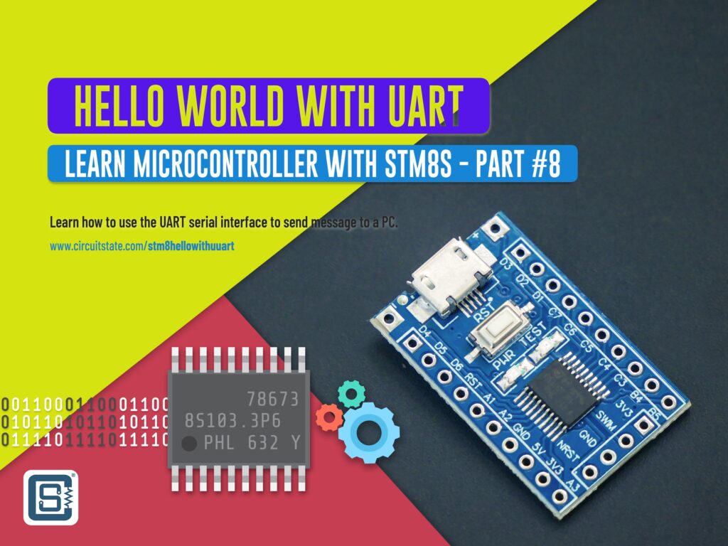
In this new tutorial, we are going to learn about a very interesting feature of a microcontroller; the ability to communicate by sending and receiving data. We will use the UART peripheral of the STM8S microcontroller to talk to a computer by writing assembly code. This opens a new world of possibilities to what you can do with a microcontroller. Being able to communicate to a PC via a digital communication interface is a practically useful feature. The keyboard, mouse and other peripherals connected to your computer communicates in a similar manner. As always, this is a follow-up tutorial in our STM8S series and if you haven’t read the previous one yet, you can do it now.
Reading Push-Buttons Through Interrupt : Learn Microcontroller with STM8S – Tutorial Part #7
Tutorial Series
- Learn the fundamentals of microcontrollers.
- Familiarize with a simple STM8S microcontroller.
- Install all the software tools and prepare your computer for programming and debugging microcontrollers.
- Get hands on experience with connecting your first microcontroller board and write a program for it.
- Learn the concepts of timers and interrupts in microcontrollers and blink an LED with what you learn.
- Learn how to make your microcontroller interact with the world by reading a push-button.
- Learn how to read a push-button using external interrupts without blocking critical code.
- Learn how to use the UART peripheral to print your first “Hello World” message to a computer.
Morse Code
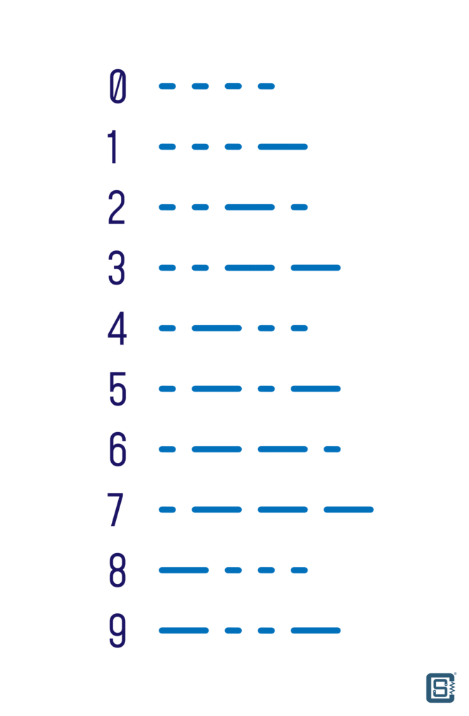
If you already do not know what a Morse Code is, it is a communication method developed by Samuel Morse in the 1830s. It is now an international communication standard called the International Morse Code. In Morse Code, information is represented as two symbols called dot and dash. As the names say, a dot is a . character and the dash is a - character. Following is the International Morse Code.
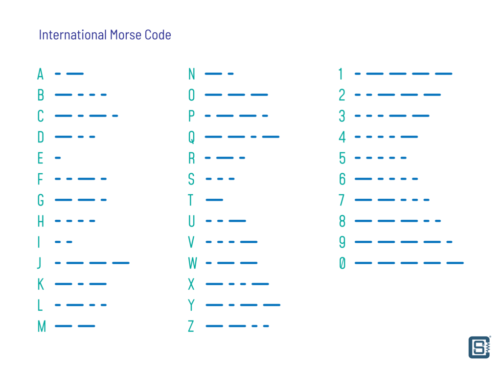
As you can see, all letters in English and the ten digits are represented as a set of dots and dashes. In a telegraph, where a signal can be turned on and off (On-Off Keying), the duration of the signal can be used to send dots and dashes by varying it. The signal medium can be voltage, current, light, sound or any other medium through which the On-Off keying can be accomplished.
The use of two discrete symbols in Morse Code makes it a binary system. Since computers also understand binary data, we can use dots and dashes for representing digital data. This is illustrated below.
We can use the GPIO pins of a microcontroller to turn it ON and OFF to create the dots and dashes. Instead of using time period for creating the discrete symbols, we can use the voltage levels. A binary 1 can be represented by a HIGH level and the binary 0 can be represented by a LOW level as shown in the image below.

Now if we connect this pin to a GPIO input and try to read the voltage levels, we can transfer digital data from pin to another. If we tie up the GPIO pins of two different microcontrollers, we can make the controllers talk to each other.
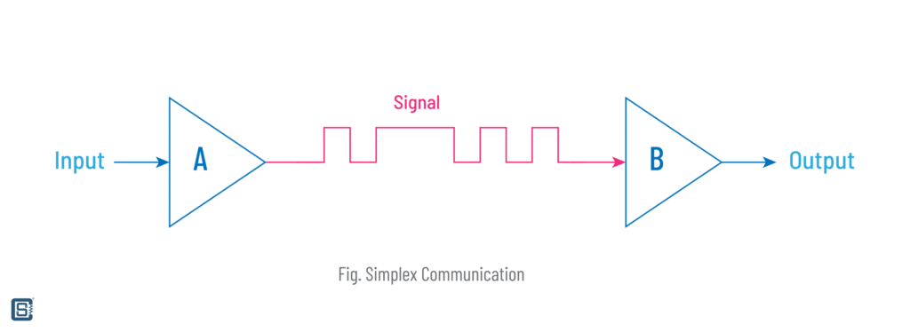
In this configuration, data can be only transferred from controller A to B. This type of communication is called a Simplex. We can transfer data in both directions by changing the type of GPIO pins on both sides. If we make the GPIO_B to output and GPIO_A to input, then the controller B will be able to send data to the controller A. This type of bidirectional communication is called a Half-Duplex.

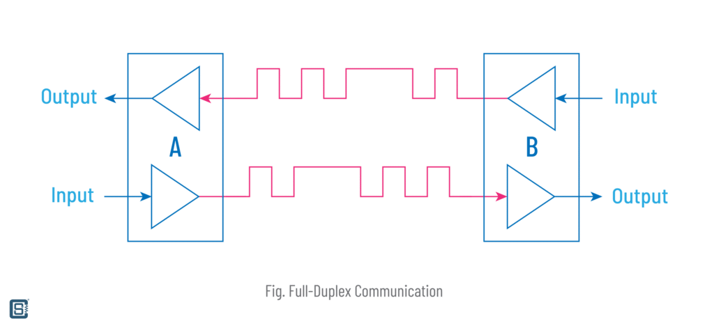
A better solution to allow simultaneous bidirectional communication is to use two GPIO pins each on both sides. An output pin will be connected to the input pin on the other side and vice versa. In this configuration, both A and B will be able to send and receive data simultaneously. This type of configuration is called a Full-Duplex.
UART
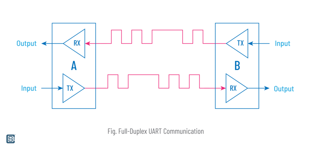
Universal Asynchronous Receiver Transmitter (UART) is a serial communication interface found in most microcontrollers. It is a similar full-duplex system we described in the last section. Since this is a standard, any microcontroller or other devices with a UART can communicate to each other without needing any extra hardware. This what the “Universal” in the name means.
What does “Asynchronous” mean? If we try to implement the system described in the last section, we will run into a few issues. First is the frequency of the On-Off keying. If the frequency of the data being sent is not matched at the receiving side, the data will be corrupted. So both the transmitter and receiver need to agree on using a common frequency. For example, if the transmitter is sending 100 bits per second, the receiving side should sample its input pin at least twice of the transmitting frequency, i.e. 200 bits per second. This is called Nyquist Theorem and it ensures that the input signal can be sampled without losing the actual information. This is why timing or frequency is very important in serial communication. UART does not use a dedicated reference clock (CLK) signal to keep the frequency the same on both the transmitting and receiving sides. Instead, UART is designed to sample the input pin at an appropriate frequency in order to catch all of the bits sent by the transmitter. The lack of a dedicated clock signal makes the interface asynchronous.
Why would anyone designing a communication interface make it more prone to issues by excluding a reference clock? The answer is simplicity. UART is indented for short range communication and can work reliably even without a clock pin. For places where a clock pin can be useful, the brother of UART, called USART (Universal Synchronous Asynchronous Receiver Transmitter) can be used. USART supports both synchronous and asynchronous communications.
Another problem we will encounter is telling where the data starts and ends. If we are sending a series of bytes continuously as bits, there should be a reliable way to tell where the first bit of a byte start. Otherwise, we can not decode the incoming data correctly.
UART Frame
UART solves this problem with a clever mechanism called a Start Bit and a Stop Bit. Along with other parts, they form the UART Frame. A data frame is simply a unit of symbols (0s and 1s) that can be repeated. Following illustration shows a single frame of UART data. Let’s explain the UART data frame.

Idle
UART is an Active-LOW line. Means, the UART communication lines will remain at a HIGH state during idle conditions. So when no data is being sent or received, the voltage on the UART lines will be a HIGH logical voltage. For a 5V system, this voltage will be 5V and for a 3.3V system, it will be 3.3V. Similarly, the logical LOW will be a 0V (usually the negative pin of the power supply).
Start Bit
The transition from the idle HIGH state to a LOW state indicates a Start Bit in UART. This indicates the start of a UART frame.
Data Bits
Just after the Start Bit, the Data Bits will start to appear. The data bits can be 1s or 0s. A binary 1 is represented with a HIGH level and a binary 0 is represented by a LOW level. The UART standard is flexible in allowing how many bits you can send in the data section. It can be 8 bits, 7 bits or 6 bits. 8 bits is the most commonly used data length. These extra configurations also mean that, two UART ports communicating each other must also agree on using the same configuration on both sides. Otherwise, they can not communicate reliably.
Parity Bit
Parity Bit is a way of ensuring data integrity during UART communications. The single bit parity allows error checking in the received message, either using Odd Parity or Even Parity algorithms. Errors can only be detected with a single Parity Bit, but can not be corrected. The receiving side can request a retransmission of the last data in case it detects an error. This can be useful in fast communications in noisy environments. The use of the Parity Bit can also be configured, allowing more flexibility in using UART.
Stop Bits
Finally, we need to end the UART frame. This is done with the help of the Stop Bit, which is a transition from the Parity Bit to the idle state again. The Stop Bits can be one or two.
As you can assume by now, soon after the idle state is achieved, we can send another UART frame containing more data. Such a succession of UART frames can allow continuous communications between two devices.
Baud Rate
A Baud is a unit to measure the symbol rate in a communication line. A symbol is simply a state change, for example a HIGH → LOW transition. In UART, the Baud is actually the bit rate, the rate at which the bits of data are sent. The term Baud is named after Émile Baudot, but the term Baud Rate is a technically incorrect one that is widely used. So if you see Baud and Baud Rate, understand that they are the same in UART.
As we said earlier, the Baud determines the speed at which you can communicate through a UART interface. The larger the Baud, the faster will be the communication. But this requires more accurate time synchronization between the devices taking part. Since the Baud is a symbol rate, it also includes the Start, Stop and the Parity Bits. As they are no the actual data, the data rate at a specified Baud will be always lower than than the Baud itself.
Connection
In order to achieve a full-duplex communication, UART requires two data lines. Only two devices can take part in a full-duplex system, though exceptions exist. These data lines are connected to some dedicated GPIO pins of the devices. A pin dedicated to sending data is called a Transmit pin and is abbreviated as TX, TXD etc. A pin dedicated to reading or receiving data is called a Receive pin and is commonly abbreviated as RX, or RXD. The TX pin of one UART devices should be connected to the RX pin of the other device. So if two devices have both TX and RX pins, they should be cross-wired. Failing to properly do this cross-connection in UART is a classical engineering mistake made by almost all engineers at least once in their lifetime.
If data needs to be only sent in one direction, the two additional pins can be removed a simplex communication can be achieved with a single TX and RX pin. In addition to the TX and RX pins, most UART interfaces also include two more pins called CTS (Clear to Send) and RTS (Ready to Send). These pins are together called Flow Control pins. These pins can be used to indicate when it is okay to send data or when to receive data. For example, if you are requesting some data from a device and the device takes some time to collect the data, you can wait for the signal from the device to start reading the data requested. Similar to RX and TX pins, RTS and CTS pins also should be cross-wired.
UART to USB Converter
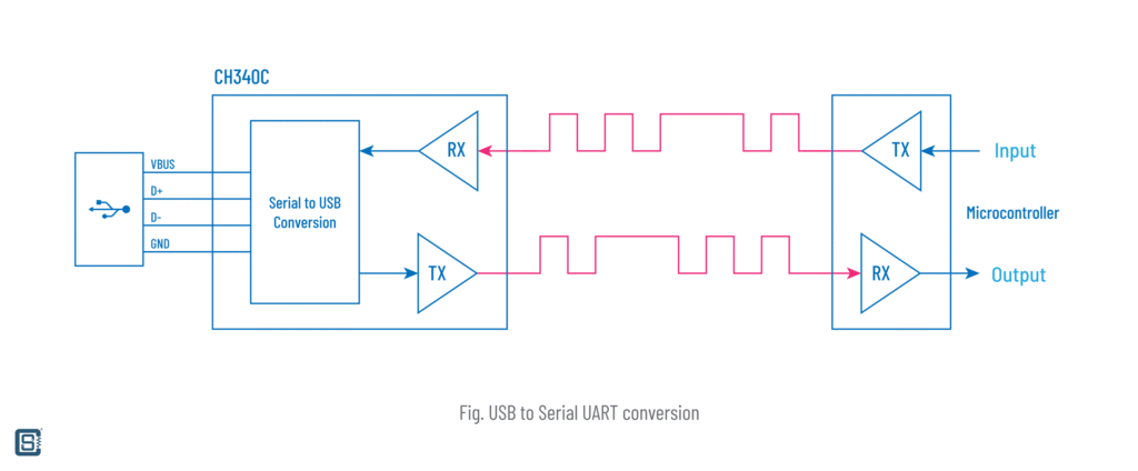
While the UART is useful for communicating between two microcontrollers, there are times when we need to send serial data to a computer. But modern computers do not have any UART ports as such. What they have in plenty is the USB, which also happen to be a serial interface expanded as the Universal Serial Bus. But since UART and USB are two different interfaces, we need something in between to translate UART data to USB data. UART-to-USB converter chips do just that. They combine a UART interface and a USB controller in a single chip. The UART side can be connected to a microcontroller or sensor. The USB side can be connected to a PC. When connected, the operating system (OS) of the PC will create what is called a Virtual Serial Port or a COM Port as it is known in Windows OS. It is a virtual port because the computer does not have an actual UART serial port but one that is emulated by the UART-to-USB converter. Regardless of being virtual, the COM port will have all of the functionalities of a typical UART port and data can be sent of received normally.
You can find cheap UART to USB converters virtually anywhere online. Three of the most popular chips are FT232 from FTDI, CP2102 from Silicon Labs and the CH340G from WCH. For this tutorial, we will use a CH340G breakout board from SparkFun – SparkFun Serial Basic Breakout – CH340G. Such modules are also called USB-to-TTL converters. We need this module to connect our STM8S board to a computer and send and receive data between the computer. If you are in India, you can get a clone of this product from Probots. Unlike the SparkFun one, this has USB-C instead of the now-dead USB-Micro. Try to buy USB-C supported products always.
CH340C
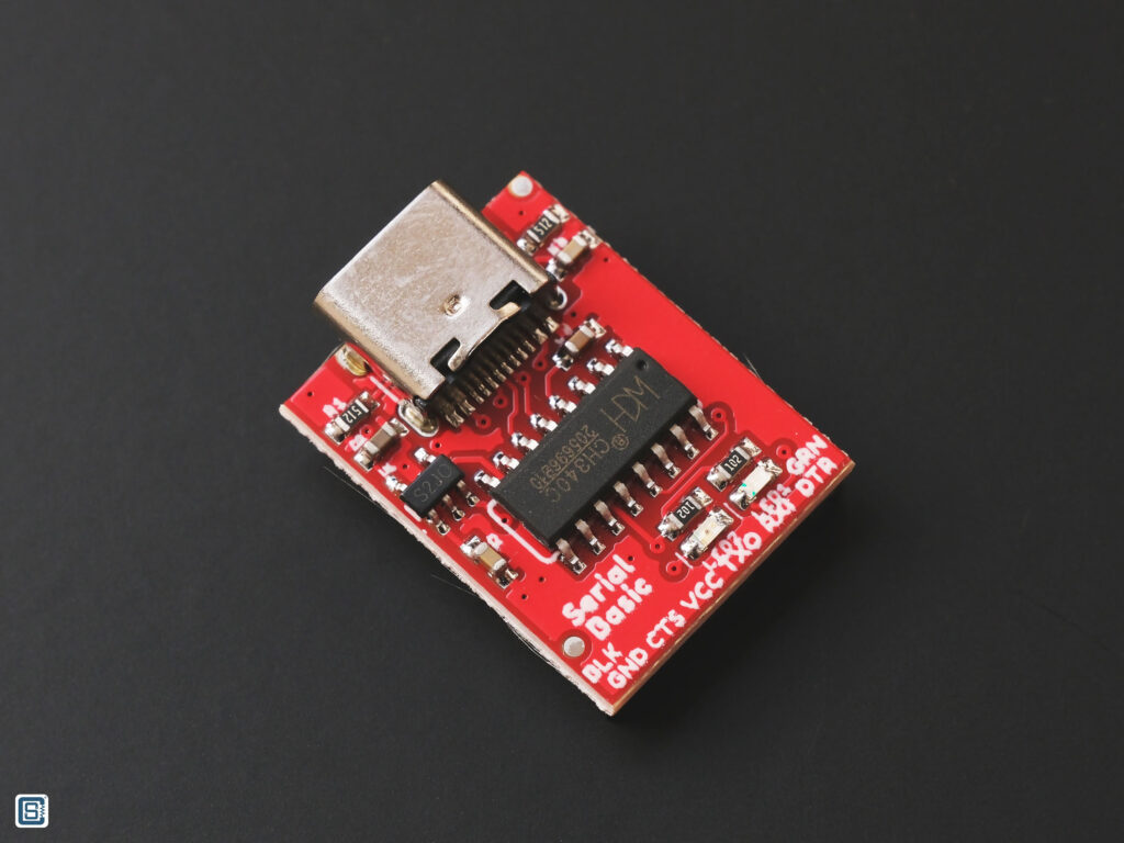
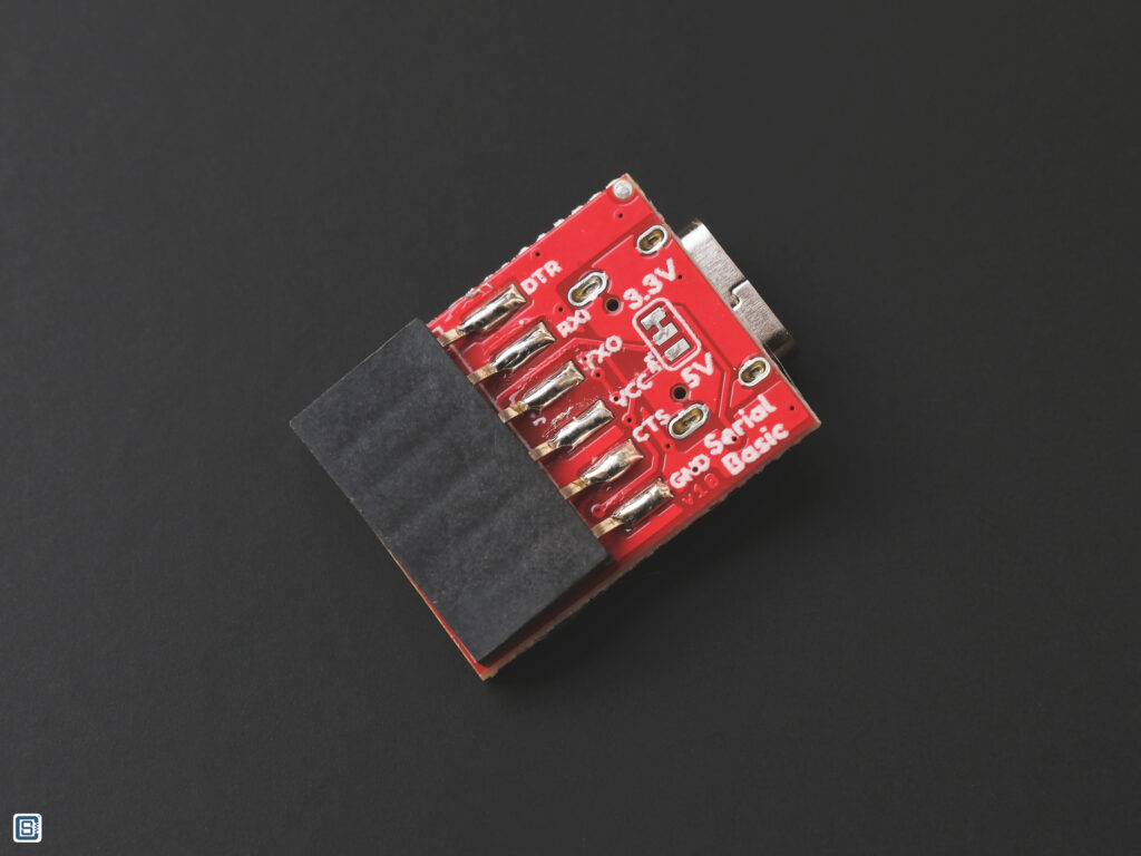
We will briefly discuss about the features of the CH340C-based UART-USB converter with a USB-C connector. As you can see from the image above, the module has a 6-pin socket header. You can use compatible header pin cables to make connections to them. There is an onboard LDO (Low Dropout) voltage regulator to convert the USB 5V to 3.3V if needed. This allows you to connect this module to a 3.3V microcontroller. There is a voltage selection jumper on the back side of the PCB. You can short the center pad to any one of the end pads to select the operating voltage. 3.3V is selected by default. Since we are using a 3.3V microcontroller here, we can proceed without any changes. The module does not have a power LED, but instead has two activity indication LEDs. These LEDs will blink when there is data flowing through the board.
Wiring
Use the following table to connect your STM8S board to the CH340C module.
| CH340C Module | STM8S-Blue |
|---|---|
VDD | NC |
GND | GND |
TXO | PD6 (UART1_RX) |
RXI | PD5 (UART1_TX) |
Since you can get 5V power from both through the STM8S board as well as the USB-UART module, you can connect the VDD/VCC pins accordingly. For example, you can connect the 5V input pin of the STM8S-Blue board to the VCC pin of the USB-UART module to get the 5V power. You then not have to connect the STM8S-Blue board to another power supply or USB. You can leave all other pins of the USB-UART converter unconnected for now.
Code
After connecting everything, power up the board and the module and check there are not power-related issues. After that, we can start uploading the code. Compile and upload the following code to your STM8S-Blue board.
.stm8
;
; STM8 Assembler - UART Hello World demo
; Version 0.1
;

.include "stm8s103.inc"

; code start
.org 0x8080

; our string
hello_msg: .asciiz "Hello World!"

start:
    MOV     CLK_CKDIVR, #0x00               ; clock setup (16MHz from HSI)
                                            ; UART setup (note that UART is by default in 8n1 mode)
    MOV     UART1_BRR2, #0x0b               ; Set the baud rate to 115200 bps, BRR2 needs to be set first
    MOV     UART1_BRR1, #0x08               ;
    BSET    UART1_CR2, #3                   ; Enable UART transmitter

    LDW     X, #hello_msg                   ; load the start address of the string

get_next_char:
    LD      A, (X)                          ; read the character at X
    JREQ    end                             ; check for null terminator, end when we're done
wait_tx_buf:
    BTJF    UART1_SR, #7, wait_tx_buf       ; wait until the TX buffer is empty (TXE bit is set)
    LD      UART1_DR, A                     ; copy the character to UART's data register
    INCW    X                               ; increment the character address
    JP      get_next_char                   ; send next character

end:
    JP end                                  ; loop forever

; interrupt vectors
.org 0x8000
INT start ; RESET handler, jump to the main program bodySerial Monitor
A Serial Monitor is a small application to send data to and receive data from Virtual Serial ports. In VS Code, you can install the Serial Monitor extension to have the ability to open serial devices right in your IDE. After uploading the code to the STM8S-Blue board, connect the CH340C module to the computer. Refresh the serial ports list in the Serial Monitor window and select the correct one. If there are no other serial devices connected to the computer, you will only see one port. Remember to also set the correct baud rate and configuration. When you click Start Monitoring button, you will start to see "Hello World!" printed repeatedly.
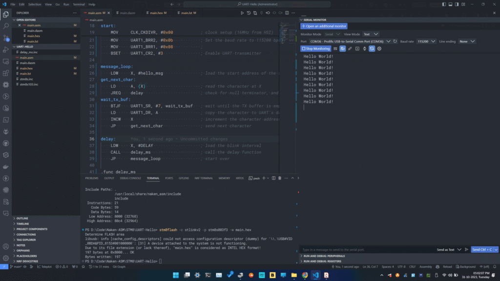
If you are not seeing the message, check the following.
- Check if the code is uploaded successfully.
- Check if the wiring is correct. Remember the cross-connection of UART pins?
- Check if you selected the right COM port. Use the Device Manager to check the COM port number of your USB-UART converter. Disconnecting and reconnecting the module to the computer can tell which one the port is.
- Check if the drivers for the CH340C module are installed correctly.
- Check if you selected the baud rate and configuration correctly.
Code Explained
We will only explain parts of the program or instructions we haven’t covered already. Please refer to the previous examples to learn about the unexplained parts.
The first interesting part is the way we have defined the constant string that we want to send through UART. We use a new assembler directive called .asciiz for this. The directive can be used to specify a string enclosed in double quotes and ends with a null character (0). The user does not have to add the null character at the end. The assembler takes care of it automatically.
This string will be placed in the data section of the program. Since we start the origin at 0x8080, the string is placed at the location starting from 0x8080.
; our string
hello_msg: .asciiz "Hello World!"Next is the start of the program. This is where the actual instructions start. We are configuring the clock here.
start:
MOV CLK_CKDIVR, #0x00 ; clock setup (16MHz from HSI)In the next three lines, we configure the UART1 of STM8S103F3. As per the datasheet of the chip, there is only one UART in STM8S103F3 called UART1 which also supports the LIN 2.1 (Local Interconnection Network) central mode.
MOV UART1_BRR2, #0x0b ; Set the baud rate to 115200 bps, BRR2 needs to be set first
MOV UART1_BRR1, #0x08 ;
BSET UART1_CR2, #3 ; Enable UART transmitterThe UART1 has the following features.
- Main Features
- 1 Mbit/s full duplex SCI
- SPI emulation
- High precision baud rate generator
- Smartcard emulation
- IrDA SIR encoder decoder
- LIN master mode
- Single wire half duplex mode
- Asynchronous communication (UART mode)
- Full duplex communication – NRZ standard format (mark/space)
- Programmable transmit and receive baud rates up to 1 Mbit/s (fCPU/16) and capable
of following any standard baud rate regardless of the input frequency - Separate enable bits for transmitter and receiver
- Two receiver wakeup modes:
– Address bit (MSB)
– Idle line (interrupt) - Transmission error detection with interrupt generation
- Parity control
- Synchronous communication
- Full duplex synchronous transfers
- SPI master operation
- 8-bit data communication
- Maximum speed: 1 Mbit/s at 16 MHz (fCPU/16)
- LIN master mode
- Emission: Generates 13-bit synch. break frame
- Reception: Detects 11-bit break frame
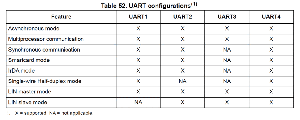
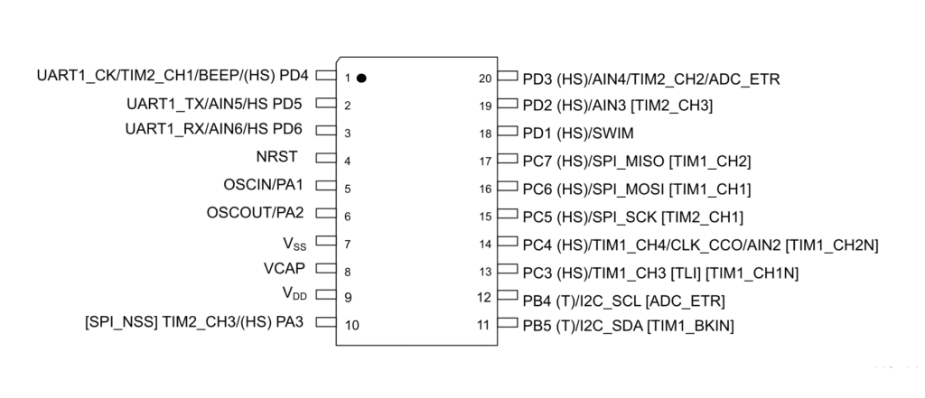
There are three pins associated with UART1.
UART1_RX– Receive pin.UART1_TX– Transmit pin. If the transmitter is disabled, the pin remains in the GPIO configuration. The idle state of the TX pin in transmit mode isHIGH.UART1_CK– Optional clock output pin for synchronous communication.
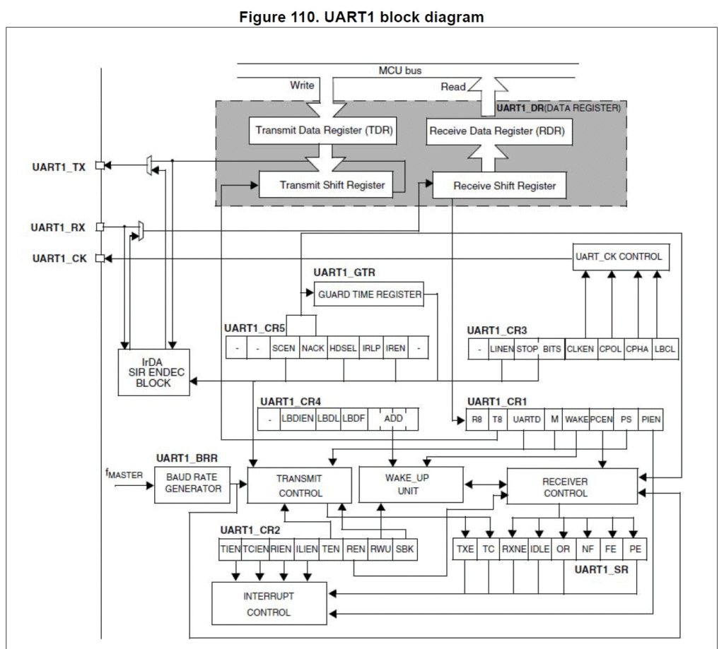
The procedure to initiate communication is as follows,
- Program the
Mbit inUART_CR1to define the word length. - Program the number of stop bits in
UART_CR3. - Select the desired baud rate by programming the baud rate registers in the following order:
UART_BRR2UART_BRR1
- Set the
TENbit inUART_CR2to enable transmitter mode. - Write the data to send in the
UART_DRregister (this clears theTXEbit). Repeat this for each data to be transmitted in case of single buffer. - Once the last data is written to the
UART_DRregister, wait untilTCis set to1, which indicates that the last data transmission is complete. This last step is required, for instance, to avoid last data transmission corruption when disabling the UART or entering Halt mode.
By default, UART1 uses 8N1 format (1 Start bit, 8 Data bits, No parity bits and 1 stop bit). So if we are using the 8N1 format, we don’t need to set that explicitly. Here, we are using the 8N1 mode.
The transmitter and receiver baud rates are set by the 16-bit UART_DIV value. The value is stored in the two registers UART1_BRR1 and UART1_BRR2. The value of UART_DIV should be a minimum of 0x16D. The UART baud rate is set when writing to the UART1_BRR1 register. So the UART1_BRR2 register should be written first.
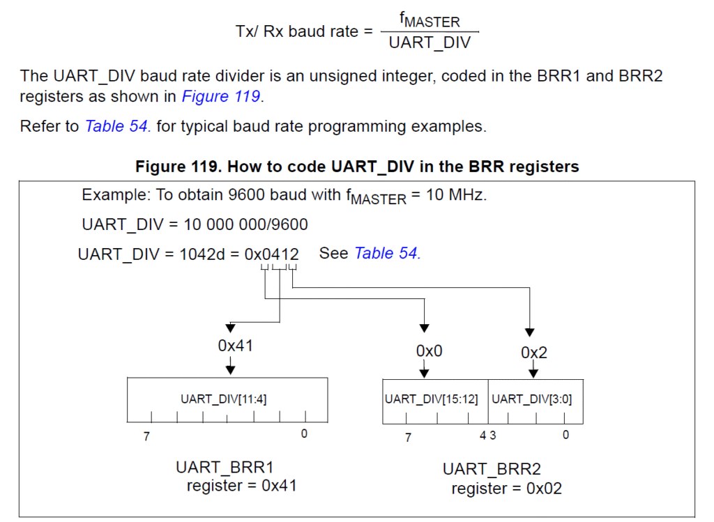
From the following table, we can get the register values for common baud rates. We are using 115200 bps here where the CPU frequency is 16 MHz.
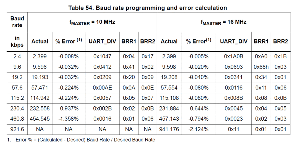
Finally, the transmitter can be enabled by setting the Transmit Enable (TEN) bit on the UART1_CR2 register.

In the next line, we move the address of the first byte of our hello_msg is stored in the X register. The hello_msg is added as an immediate value using # as a prefix. We will later use this address to send one byte at a time through the UART.
LDW X, #hello_msg ; load the start address of the stringLD
The LD is a new instruction. It loads a single byte from the source to the destination. Here we are loading the value at the memory location pointed by the X index register. The brackets around X indicates that we are using the direct-indexed addressing mode.
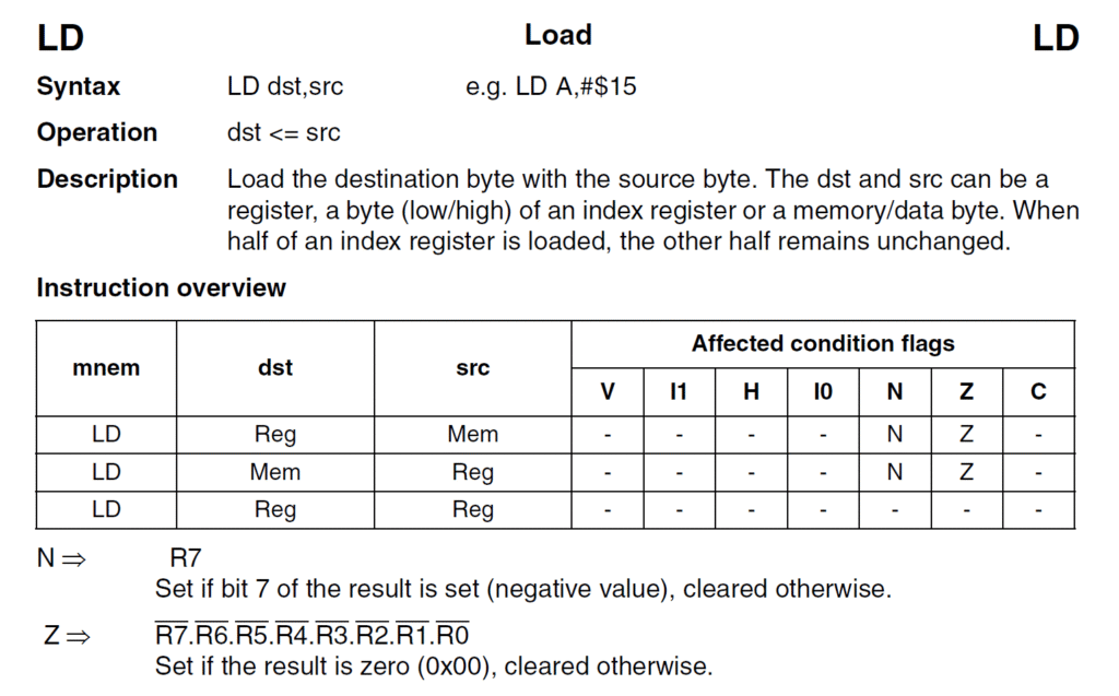
In the following line, we are loading the first byte of the the hello_msg, which is “H” to the Accumulator (A) register.
get_next_char:
LD A, (X) ; read the character at XJREQ
In the next line, we use the JREQ to check if the Zero flag bit in the CC register is set. Since LD instruction affects the CC register when moving data from or to the memory, we can use the Z flag to determine if the value we just loaded is 0. Since our original message string is NULL terminated, we can use the JREQ instruction to end the program once the message is completely sent. end here is an another label.
JREQ end ; check for null terminator, end when we're doneBTJF
This is an interesting instruction. BTJF stands for Bit Test and Jump if False. This instruction takes in three parameters: destination byte, bit position and a label (address). In the following line, we are checking if the bit TXE (Transmit Data Register Empty) on the UART1_SR (0xC0 at reset) status register. The TXE bit is set when the hardware finishes transmitting the content of the UART1_DR data register. The state of TXE bit is 1 after a reset, indicating that the transmit data register is empty.
wait_tx_buf:
BTJF UART1_SR, #7, wait_tx_buf ; wait until the TX buffer is empty (TXE bit is set)
So until the TXE bit becomes 1, the wait_tx_buf will act as a loop, waiting for the transmit operation to complete, which is exactly what we want.
If the TXE bit is 1, we won’t jump but proceed to the next instruction. The next line loads the first character, now available on A, to the UART data register. As soon as a data is written to the data register, the TXE bit is set to 0 automatically, and the transmit process begins.
LD UART1_DR, A ; copy the character to UART's data registerINCW
Since we have more characters left to send, we can increment the address pointer to the message once. The instruction INCW (Increment Word) is used to increment the content (current address to the message) of X register. After incrementing, X will now point to the “e” character.
INCW X ; increment the character addressAfter that, we can repeat the same steps used to send the first character to send the remaining characters. In the following line, we jump to the get_next_char label to send the next character.
JP get_next_char ; send next characterWhen all of the message bytes are sent, line 26 will cause the processor to go to an infinite loop.
end:
JP end ; loop foreverYou can connect a USB-Serial module to the PD5 (TX) and PD6 (RX) pins and see the message printed by the STM8.
The previous program only sends the message once after reset. Why not send the message periodically? The following code does that. We are combining the same type of loop function we used in the previous examples. You should be able to read and understand how it works on your own. With this, we can complete this tutorial.
.stm8
;
; STM8 Assembler - UART Hello World demo
; Version 0.2
;
F_CPU EQU 16000000 ; CPU clock frequency, required by delay routines
DELAY EQU 500 ; Blink interval in ms
.include "stm8s103.inc"
; code start
.org 0x8080
; our string
hello_msg: .asciiz "Hello World!\n"
start:
    MOV     CLK_CKDIVR, #0x00   ; clock setup (16MHz from HSI)
; UART setup (note that UART is by default in 8n1 mode)
MOV     UART1_BRR2, #0x0b   ; Set the baud rate to 115200 bps, BRR2 needs to be set first
MOV     UART1_BRR1, #0x08   ;
BSET    UART1_CR2, #3       ; Enable UART transmitter
message_loop:
LDW X, #hello_msg ; load the start address of the string
get_next_char:
    LD  A, (X)   ; read the character at X
JREQ delay ; check for null terminator, and wait if true.
wait_tx_buf:
    BTJF  UART1_SR, #7, wait_tx_buf  ; wait until the TX buffer is empty (TXE bit is set)
LD UART1_DR, A ; copy the character to UART's data register
INCW X ; increment the character address
JP get_next_char ; send next character
delay:
LDW X, #DELAY ; load the blink interval
CALL delay_ms ; call the delay function
JP message_loop ; start over
.func delay_ms
loop_ms:
LDW Y, #((F_CPU / 1000) / 3) ; set the inner loop to the equivalent of 1000us
loop_cycles:
DECW Y ; decrement the inner loop
JRNE loop_cycles ; loop until Y is zero
DECW X ; decrement the number of milliseconds
JRNE loop_ms ; loop until X is zero
RET
.endf
; interrupt vectors
.org 0x8000
INT start ; RESET handler, jump to the main program bodyLinks
- NakenASM – Official Website
- NakenASM – GitHub
- STM8 Assembler Playground
- STM8S Series – Official Product Page
- STM8S103F3 Datasheet [PDF]
- AN2752 – Getting Started with STM8S and STM8AF Microcontrollers [PDF]
- PM0044 – STM8 CPU Programming Manual [PDF]
- RM0016 – STM8S and STM8AF Series 8-Bit Microcontrollers [PDF]
- STM8 Product Lineup [PDF]
Short Link
- A short URL to this page – https://www.circuitstate.com/stm8hellowithuart


