Getting Started with WizFi360-EVB-Pico – RP2040 and Wi-Fi Development Board from WIZnet
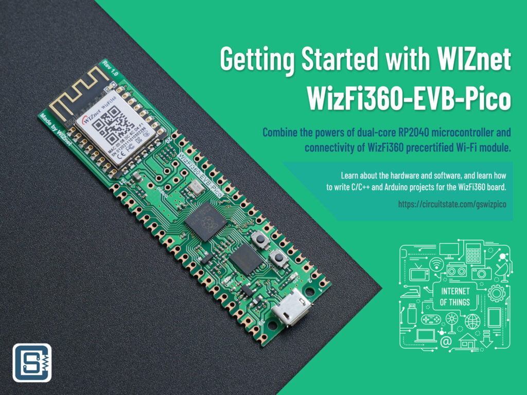
The Raspberry Pi Pico and the RP2040 microcontroller have become the most trending names in the maker space. It is no surprise why a product gets adopted so widely and so fast when that product is cheap and feature-packed. RP2040 is a generic ARM Cortex-M0+, dual-core 32-bit microcontroller with so many nifty features which make it a straight grab for any maker or hobbyist. RP2040 also won’t bankrupt you as it only costs $1 (INR 70) and best of all, it is available everywhere and you don’t have to wait for 32 weeks to get it 😂
Since RP2040 is a perfectly timed product it wasn’t long before everyone started making boards and modules using it. Even we are making a series of RP2040-based boards called Mitayi. More about that will be in an upcoming post. Now, WIZnet, a South Korean semiconductor company, has introduced their new RP2040-based board by combining their WizFi360 pre-certified Wi-Fi module. WizFi360 is based on the W600 SoC from Winnermirco, a Chinese semiconductor company. The new development/evaluation board is called WizFi360-EVB-Pico.
WIZnet is now conducting a global IoT-design competition where the participants have to use the WizFi360 module in their projects and demonstrate the use of the Wi-Fi connectivity feature. WIZnet is sending free hardware for applicants submitting ideas for projects. We also received a couple of hardware from WIZnet India and among them is the WizFi360-EVB-Pico. The board or module is not yet popular in the Indian market and we could not find it at any Indian stores we regularly buy from. We were able to get the WizFi360 products only by contacting the WIZnet India division directly. Thanks to Muralidharan from WIZnet India for arranging the boards. WIZnet also has products in the Ethernet/Networking category with many open-source board designs. Find more about them at their store.
In this article, we will try to explore the design and features of the WizFi360-EVB-Pico board and learn how to write applications for it. The window for contest entry is still open when we are writing this. The last date is the 31st of August of 2022. So you have just two days left to submit your idea. If in case you did not receive the free hardware, you can buy the board from WIZnet’s official stores.
We can develop embedded firmware for you
CIRCUITSTATE can develop embedded firmware for any microcontroller/microprocessor including 8051, PIC, AVR, ARM, STM32, ESP32, and RISC-V using industry-leading SDKs, frameworks, and tools. Contact us today to share your requirements.

Contents
Features & Specifications
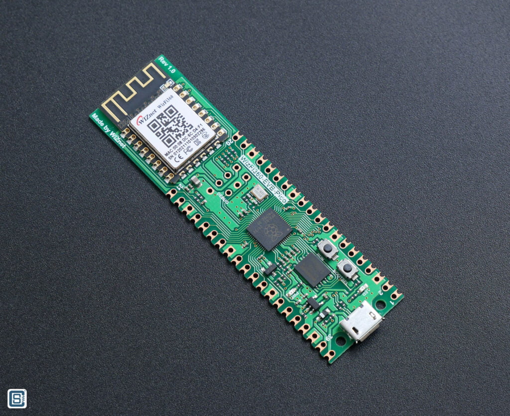
WizFi360-EVB-Pico
- RP2040 microcontroller with 2 MByte (16 Mbit) Flash
- Dual-core cortex M0+ at up to 133MHz
- 264kByte multi-bank high-performance SRAM
- External Quad-SPI Flash with eXecute In Place (XIP)
- Includes WizFi360-PA
- Micro-USB B port for power and data (and for reprogramming the Flash)
- 40 pin 21×51 ‘DIP’ style 1mm thick PCB with 0.1″ through-hole pins also with edge castellations
- 3-pin ARM Serial Wire Debug (SWD) port
- Built-in 3.3V LDO
- Power and Debug LEDs
- Two push-buttons for RESET and BOOTSEL
- Open-source design (Altium)
WizFi360-PA
- WiFi 2.4G, 802.11 b/g/n
- Supports Station / SoftAP / SoftAP+Station operation modes
- Supports “Data pass-through” and “AT command data transfer” mode
- Supports serial AT command configuration
- Supports TCP Server / TCP Client / UDP operating mode
- Supports configuration of operating channel 1 ~ 13
- Supports auto 20MHz / 40MHz bandwidth
- Supports WPA_PSK / WPA2_PSK encryption
- Serial port baud rate up from 600bps to 2Mbps with 16 common values
- Supports up to 5 TCP / UDP links
- Obtaining IP address automatically from the DHCP server (Station mode)
- DHCP service for Wireless LAN clients (AP mode)
- Supports DNS for communication with servers by domain name
- Supports “Keep-Alive” to monitor TCP connection
- Supports “Ping” for monitoring network status
- Built-in SNTP client for receiving the network time
- Supports built-in unique MAC address and user configurable
- Supports firmware upgrade by UART Download / OTA (via WLAN)
- Industrial grade (operating temperature range: -40 ° C ~ 85 ° C)
- KC, CE, FCC, TELEC certification
W600
- Hardware
- 32-bit ARM Cortex-M3 CPU, operating frequency 80MHz
- Integrated 288KB RAM
- Integrated 1MB Flash
- 8 channel DMA controller
- Integrated 2.4GHz RF transceiver, supports IEEE 802.11 protocol.
- Integrated PA/LNA/TR-Switch
- Integrated 32.768 KHz oscillator
- Integrated LDO, power supply control and power-on-reset.
- Cryptographic hardware accelerators for PRNG, SHA1, MD5, RC4, DES, 3DES, AES and CRC.
- Interface
- SDIO 2.0 Device controller, supports SDIO 1-/4-bit and SPI operating mode. Operating frequency 0~50MHz.
- 2 x UART interface, supports RTS/CTS, baud rate: 1200bps~2Mbps.
- 1 x High speed SPI controller (0~50MHz)
- 1 x I2C (100/400 KHz)
- 5 channel PWM (2 channel PWM capture) with maximum frequency of 20MHz.
- 1 x I2S (full-duplex, 32-192KHz)
- 1 x ISO/IEC 7816
- Network and Protocol
- Supports GB15629.11-2006, IEEE802.11 b/g/n/e/i/d/k/r/s/w
- Supports WAPI2.0
- Supports Wi-Fi WMM/WMM-PS/WPA/WPA2/WPS
- Support for Wi-Fi Direct
- Supports EDCA channel access mode
- 20/40M bandwidth
- Supports STBC, GreenField, Short-GI, support reverse transmission
- Supports RIFS frame interval
- AMPDU, AMSDU
- Supports IEEE802.11n MCS 0~7, MCS32, transmission rate is up to 150Mbps
- Support for Short Preamble at 2/5.5/11Mbps rate delivery
- Supports HT-immediate Compressed Block Ack, Normal Ack, No Ack response mode
- Supports CTS to self
- AP support functions
- Supports simultaneous AP and STA modes
- In a BSS network, multiple multicast networks are supported, and each multicast network is supported in different encryption modes. The maximum number of multicast networks and the STAs that are connected to the network can be up to 32.
- When BSS network support is used as an AP, the total number of supported sites and groups is 32, and 16 sites are supported in the IBSS network
- Receive sensitivity:
- 20MHz MCS7 @ -71dBm
- 40MHz MCS7 @ -68dBm
- 54Mbps @ -73dBm
- 11Mbps @ -86dBm
- 1Mbps @ -95dBm
- Allowable carrier frequency deviation: 50ppm
- Allowable sampling frequency deviation: 50ppm
- Support different encryption modes STA communication
- Support a variety of different receive frame filtering options
- Support for monitoring
- Power Supply
- 3.3V power supply
- Support PS-Poll, U-APSD low power management
- Standby power consumption is less than 10uA
- Packaging
- QFN32, 5mm x 5mm package
WizFi360-PA Module
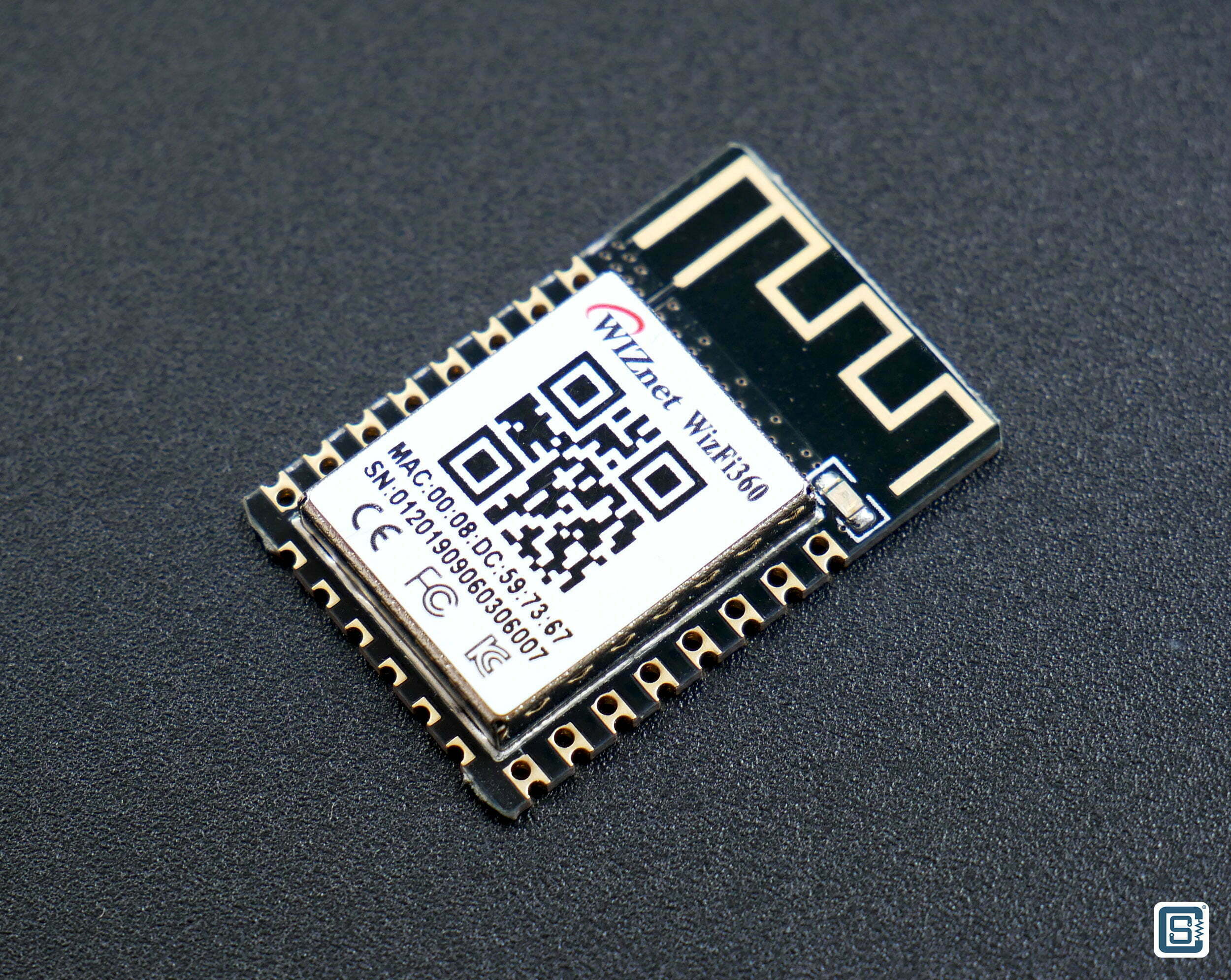
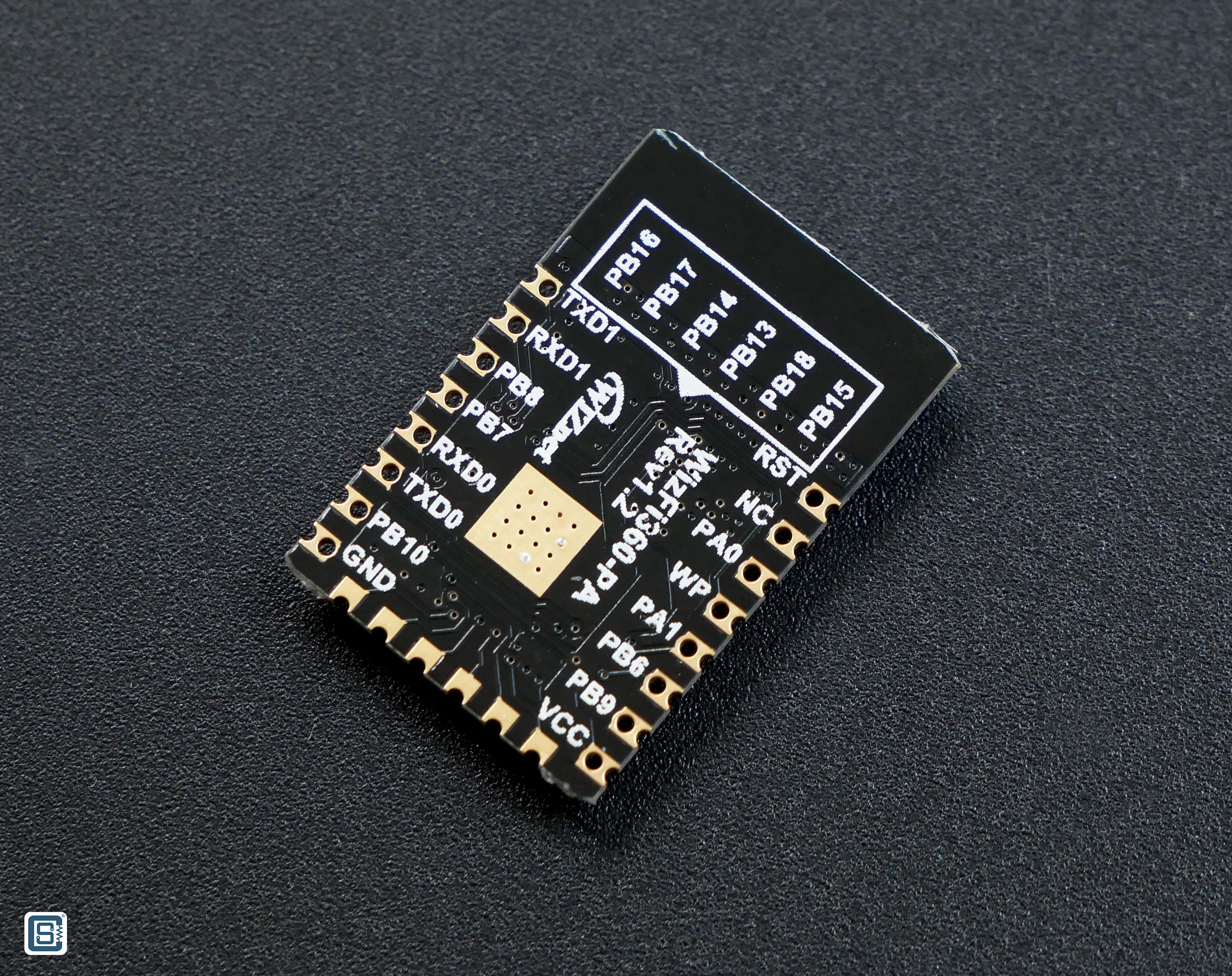
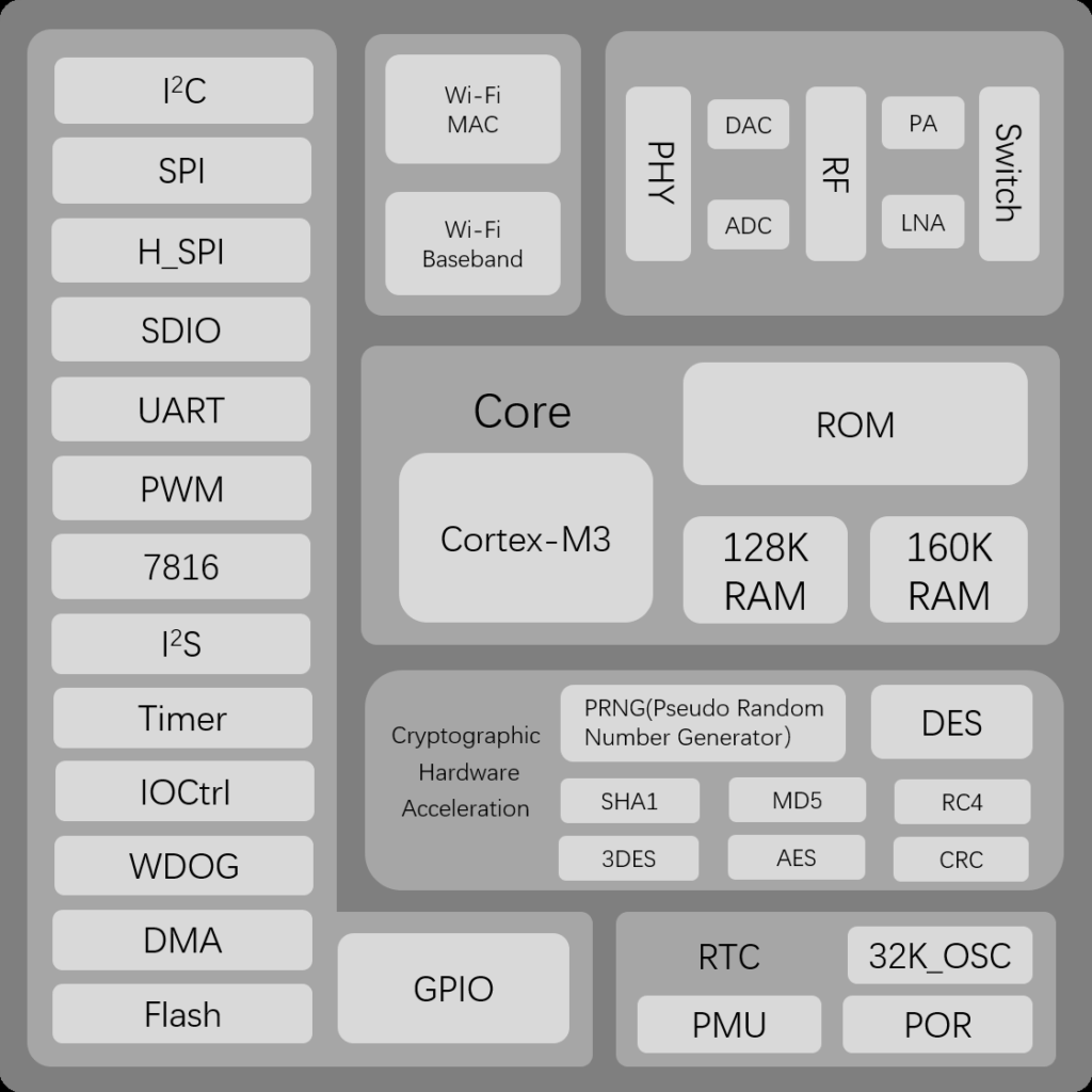
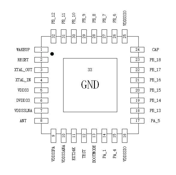
WizFi360-PA is a precertified Wi-Fi module based on the W600 wireless SoC. W600 is a single-core ARM Cortex M3 microcontroller that integrates a Wi-Fi radio and other peripherals. The CPU can run at a maximum clock of 80MHz. It has an SRAM of 288 KB and a flash memory of 1 MB. The chip has a rich set of peripherals and cryptographic accelerators. The nominal working voltage is 3.3V and the QFN-32 measures just 5 x 5mm. It is a close competitor to the ESP8266EX and ESP8285 from Espressif. The main difference between them is that the ESP8266 can run at double the clock speed of the W600.
WizFi360-PA has the same dimensions and almost the same pinouts as the ESP12E or ESP12F module. This makes both of them footprint and pin-compatible. But unlike the ESP12F module, you get a dedicated SPI for your communication requirements with the WizFi360 module which can be very useful for many applications. In the ESP12F module, the SPI pins are used to interface the flash chip and therefore the pins cannot be used for anything else. But any hardware is good only to the extent of how good the software and documentation support is. WizFi360-PA comes with a PCB trace antenna and the module is certified by CE, FCC, KC, K-MIC(TELEC), RoHS, and REACH. WizFi360-PA has a sibling named WizFi360-CON that has a U.FL connector instead of a PCB antenna. Everything else is the same. There are four more boards that are based on WizFi360-PA.
- WizFi360-EVB-Shield – designed as a shield for the Arduino Uno board.
- WizFi360-EVB-Mini – designed like the Node-MCU (ESP8266) board, but it can not run application code directly on it.
- WizFi360io
- WizFi360io-H
Pinout
WizFi360-EVB-Pico
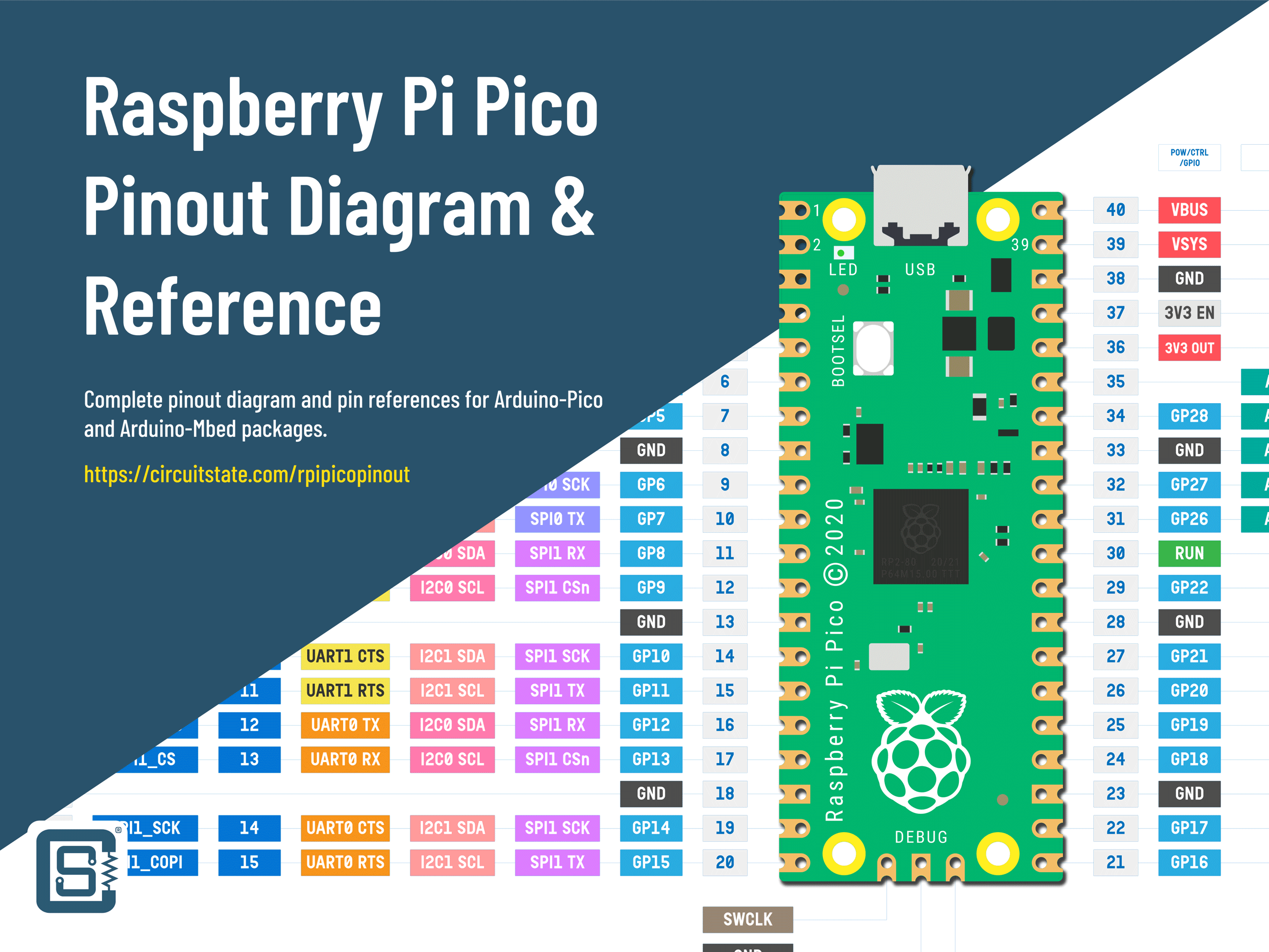
Raspberry Pi Pico RP2040 Microcontroller Board – Pinout Diagram & Arduino Pin Reference
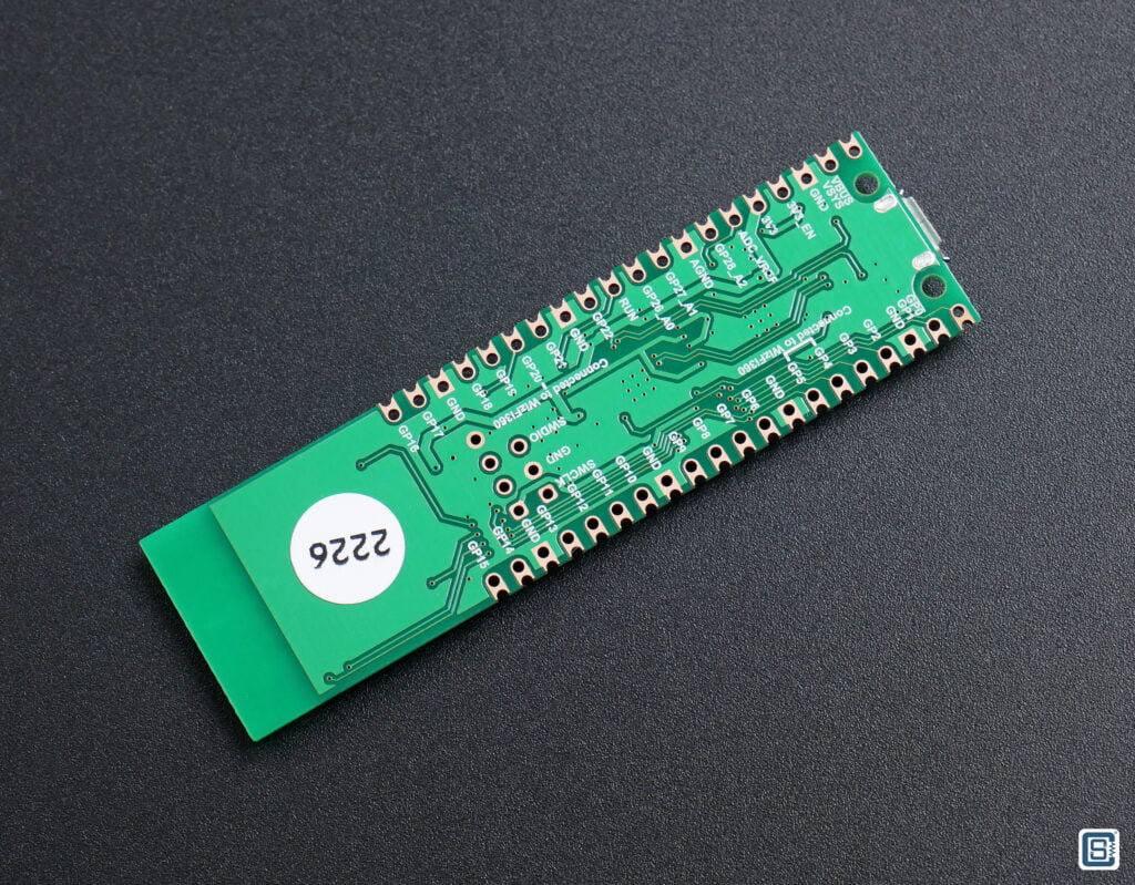
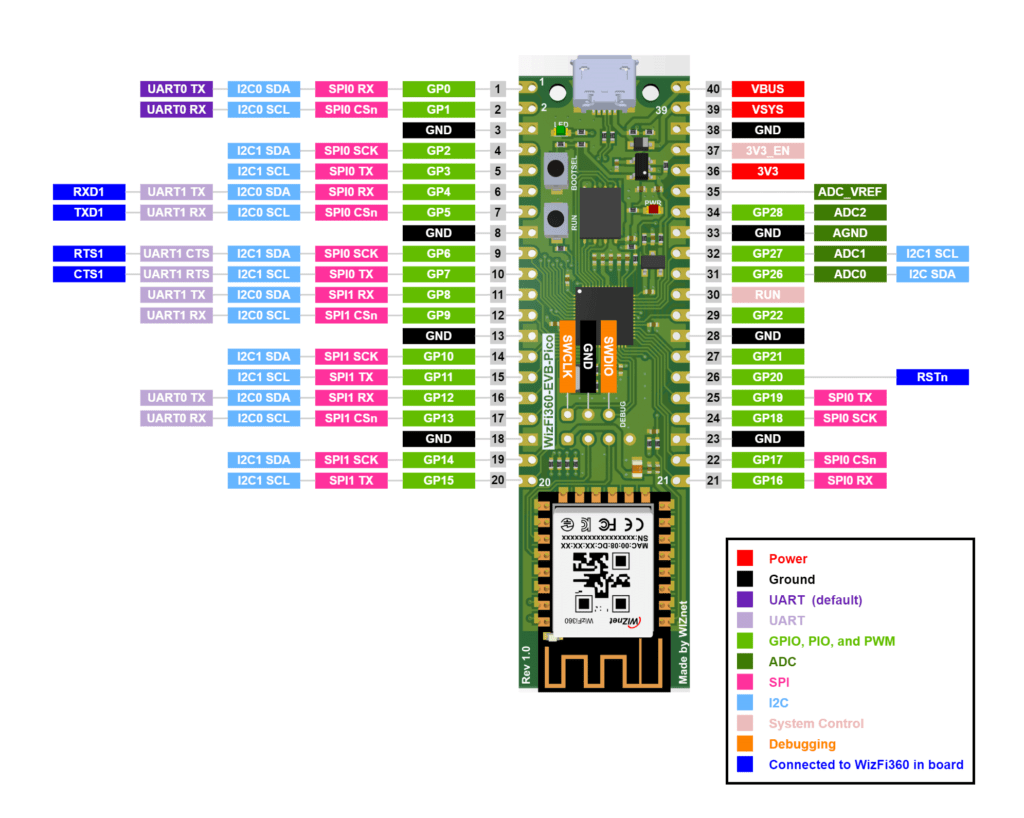
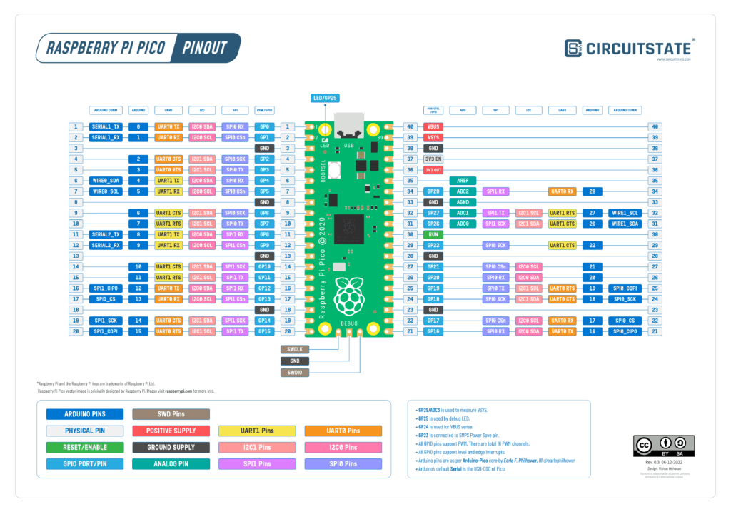
WIZnet has provided a pinout diagram for the WizFi360-EVB-Pico. You can use our pinout diagram of RPi Pico to better figure out the pins. The following GPIO pins of RP2040 are assigned with special functions including communicating with the Wi-Fi module. Try to not use these pins for anything else.
| I/O | Pin Name | Description |
|---|---|---|
| O | GPIO4 | Connected to RXD1 on WizFi360 |
| I | GPIO5 | Connected to TXD1 on WizFi360 |
| O | GPIO6 | Connected to RTS1 on WizFi360 |
| I | GPIO7 | Connected to CTS1 on WizFi360 |
| O | GPIO20 | Connected to RST on WizFi360 |
| I | GPIO24 | VBUS sense – high if VBUS is present, else low |
| O | GPIO25 | Connected to user LED |
| I | GPIO29 | Used in ADC mode (ADC3) to measure VSYS/3 |
The following pins have almost similar functions as of RPi Pico. Since WizFi360-EVB-Pico uses a linear LDO instead of a switching regulator, some of the functions are a little different.
| Pin No. | Pin Name | Description |
|---|---|---|
| PIN40 | VBUS | Micro-USB input voltage, connected to micro-USB port pin 1. Nominally 5V. |
| PIN39 | VSYS | Main system input voltage, which can vary in the allowed range 4.3V to 5.5V, and is used by the on-board LDO to generate the 3.3V . |
| PIN37 | 3V3_EN | Connects to the on-board LDO enable pin. To disable the 3.3V (which also de-powers the RP2040 and WizFi360), short this pin low. |
| PIN36 | 3V3 | Main 3.3V supply to RP2040 and WizFi360, generated by the on-board LDO. |
| PIN35 | ADC_VREF | ADC power supply (and reference) voltage, and is generated on WizFi360-EVB-Pico by filtering the 3.3V supply. |
| PIN33 | AGND | Ground reference for GPIO26-29. |
| PIN30 | RUN | RP2040 enable pin, To reset RP2040, short this pin low. |
Note that the Arduino pinouts given in our pinout diagram are as per the default pin mapping available in the Arduino-Pico core developed by Earle F. Philhower, III. The pinouts will be different when you use the Arduino-Mbed-RP2040 core from Arduino. Also, different board variants can also alter pin mapping in their respective pins_arduino.h file.
If you are new to the RP2040 microcontroller and the Raspberry Pi Pico board, we have a great tutorial to get you started.
Getting Started with Raspberry Pi Pico : RP2040 Microcontroller Board – Pinout, Schematic and Programming Tutorial
WizFi360-PA
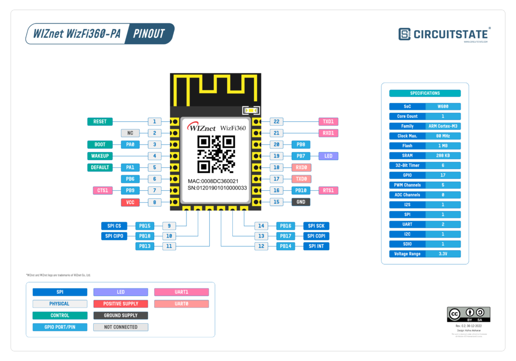
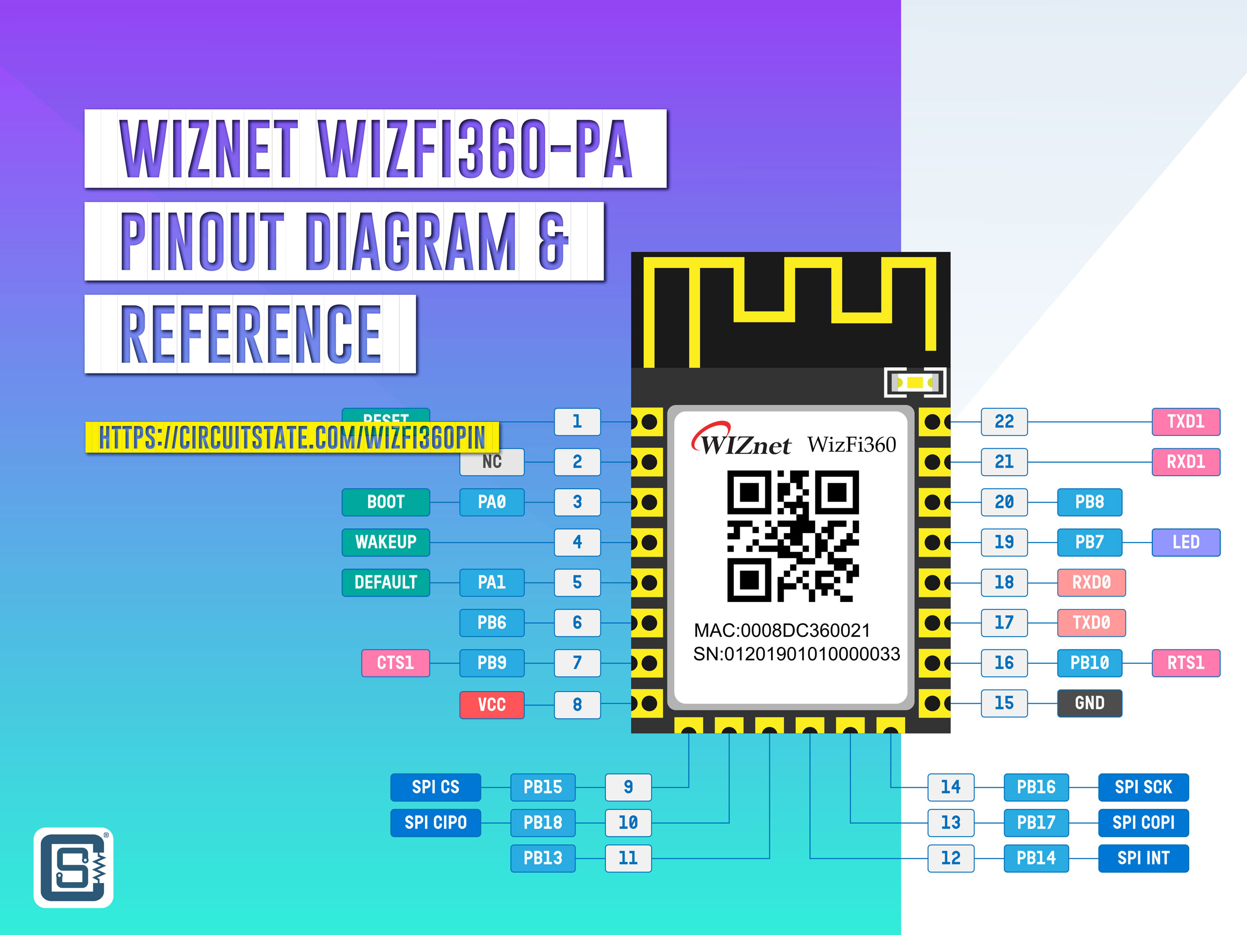
WIZnet WizFi360-PA Wi-Fi Module – Pinout Diagram & Reference
| Pin No. | Pin Name | Type | Description |
|---|---|---|---|
| 1 | RST | Input | Module Reset Pin (Active Low) |
| 2 | NC | – | Reserved |
| 3 | PA0 | I/O | BOOT Pin (Active low) When power on or reset is low, it operates in Boot mode. In the normal operating mode, this pin can be controlled by AT command. |
| 4 | WP | Input | WAKE-UP Pin (Active High) If the wake-up pin is high in Standby mode, the WizFi360 is reset to the normal operating mode. |
| 5 | PA1 | Input | Pull down over 3s for taking effect. UART1’s current parameter changes to the default value (please refer to the AT+UART_CUR command in WizFi360 AT command manual). |
| 6 | PB6 | I/O | This pin can be controlled by AT command. |
| 7 | PB9 | Input | CTS Pin of UART1 If you don’t use the CTS function, this pin can be controlled by AT command. |
| 8 | VCC | Power | Power Pin (Typical Value 3.3V) |
| 9 | PB15 | I/O | CSn Pin of SPI If you don’t use the SPI function, this pin can be controlled by AT command. |
| 10 | PB18 | I/O | MISO Pin of SPI If you don’t use the SPI function, this pin can be controlled by AT command. |
| 11 | PB13/SPI_EN | I/O | Enable Pin of SPI When power is applied or reset, this pin is checked to set the module mode. High or NC – UART Mode (Default) Low – SPI Mode |
| 12 | PB14 | I/O | INTn Pin of SPI If you don’t use the SPI function, this pin can be controlled by AT command. |
| 13 | PB17 | I/O | MOSI Pin of SPI If you don’t use the SPI function, this pin can be controlled by AT command. |
| 14 | PB16 | I/O | CLK Pin of SPI If you don’t use the SPI function, this pin can be controlled by AT command. |
| 15 | GND | Power | Ground Pin |
| 16 | PB10 | Output | RTS Pin of UART1 If you don’t use the RTS function, this pin can be controlled by AT command. |
| 17 | TXD0 | Output | TXD Pin of UART0 (AT command port) |
| 18 | RXD0 | Input | RXD Pin of UART0 (AT command port) |
| 19 | PB7 | Output | LED Light output (Active High). Go to High while each TX/RX packet and then back to Low. Note: It has been connected to the onboard LED for WizFi360-PA |
| 20 | PB8 | I/O | This pin can be controlled by AT command. |
| 21 | RXD1 | Input | RXD Pin of UART1 (Debug port) |
| 22 | TXD1 | Output | TXD Pin of UART1 (Debug port) |
W600
Schematic
The WizFi360-EVB-Pico has an open-source hardware design. The Altium design source files can be downloaded from the official repository.
The schematic replicates most of the features you will find on the official Raspberry Pi Pico board + a few improvements. The WizFi360-EVB-Pico has power and debug LEDs and two push-buttons dedicated to RESET and BOOTSEL controls. The board also has the same pinout as the official Pico (but the pins assignments in the software are a little different which we will see later).
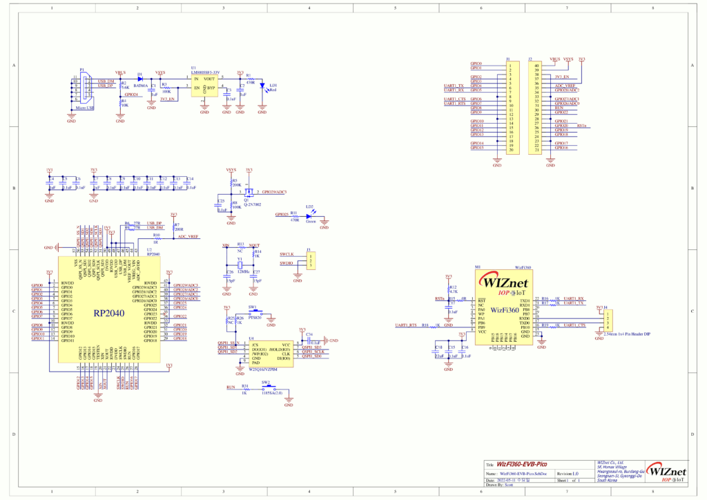
The 3.3V voltage regulator used is LM8805SF5-33V with a dropout voltage of 0.6V at 600mA. The main power comes from a micro USB through a BAT60A Schottky diode. A 2N7002 N-channel MOSFET connects VSYS to the ADC pin GPIO29 for input voltage measurement. The flash memory used is a 16 Mbit W25Q16JVZPIM in WSON-8 package from Winbond. WizFi360-PA has two UARTs. UART1 (TX1 and RX1) of WizFi360-PA is connected to UART1 (GPIO4 and GPIO5) of RP2040 along with the flow control pins RTS and CTS. The GPIOs 4 and 5 of RP2040 are actually I2C0 pins on the Arduino board definition for official Pico. But this is swapped between the UART1. UART0 of WizFi360-PA is connected to a breakaway header where you can use it to communicate with other peripherals or for debugging. GPIO20 of RP2040 is connected to the reset pin of the WizFi360-PA module.
PCB
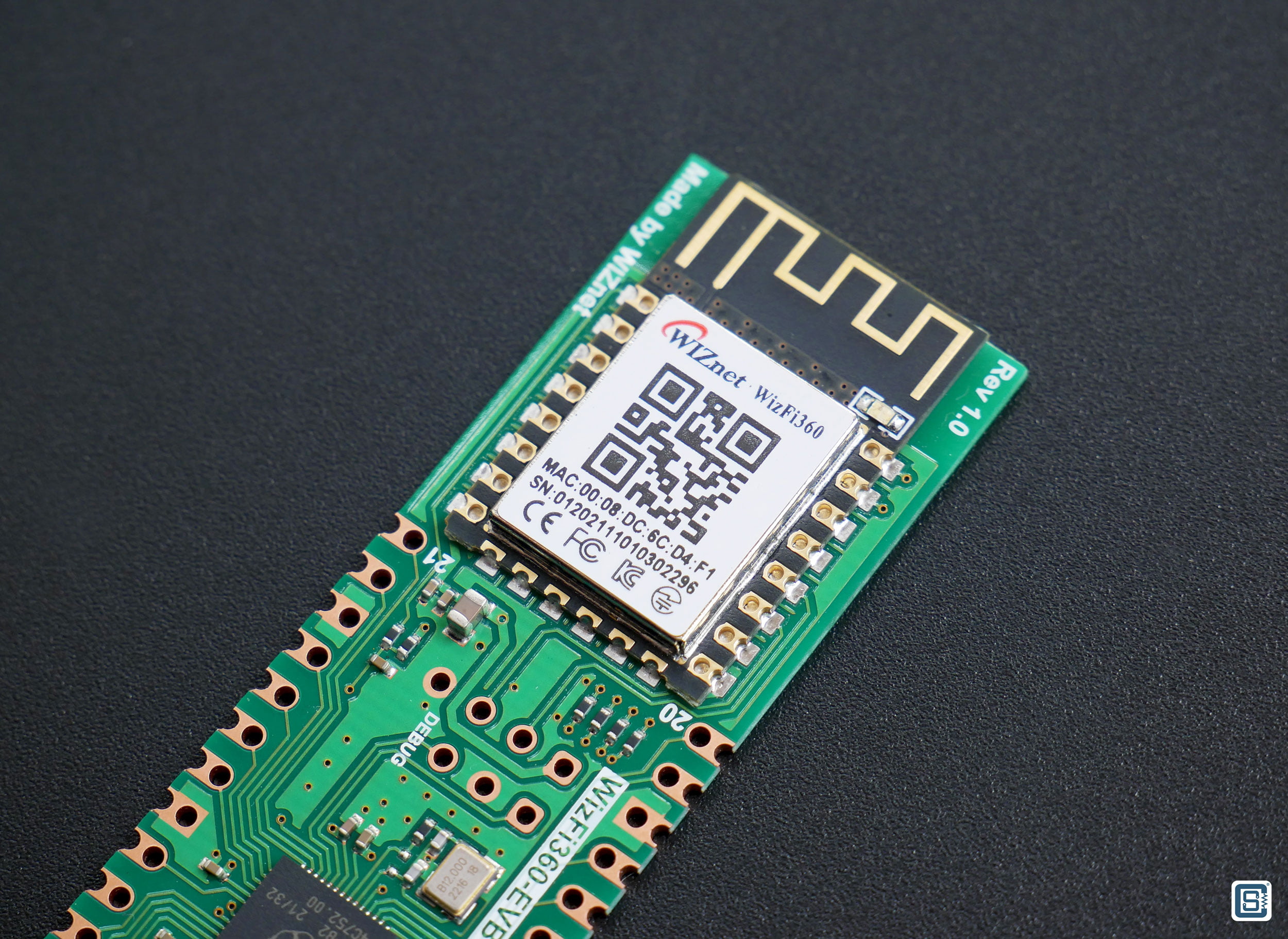
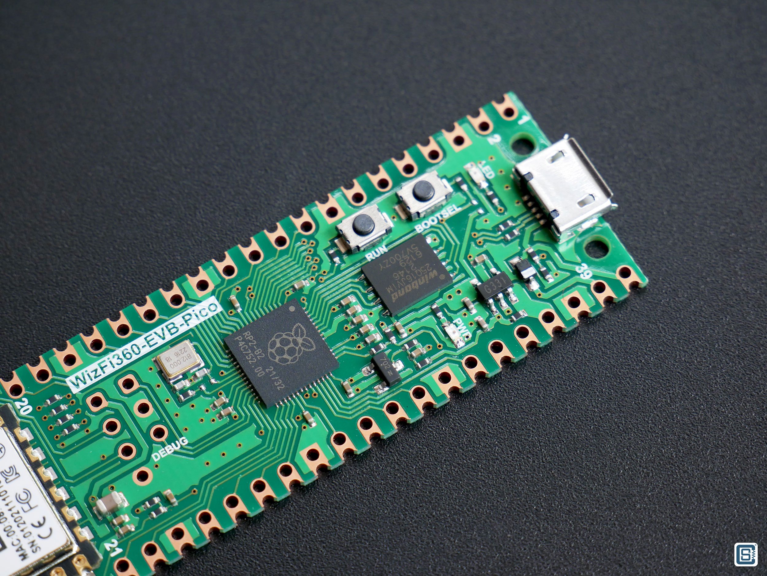
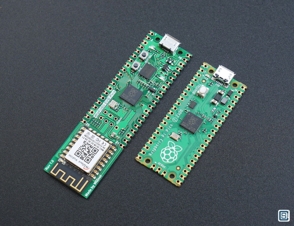
The WizFi360-EVB-Pico PCB has the same pin layout as that of RPi Pico with castellated holes. Two mounting holes have been removed to make space for the WizFi360-PA module. We really wish that the WizFi360-EVB-Pico had a USB Type-C receptacle instead of a Micro USB. Components on the PCB are arranged very neatly and the PCB has good quality. In fact, the silkscreen quality is the best we have seen on any PCB. It’s just so precise and clear. We wonder how they have done it. All PCB manufacturers should try to provide that kind of quality for their silkscreen. The onboard RESET button makes it easy to recover from “bad flashes”. In addition to the three-pin SWD header, the board has a four-pin header for the UART debugging port of the WizFi360-PA.
Programming
So how does the WizFi360-EVB-Pico work? Well, as we have seen before, we have two programmable things on the board; an RP2040 microcontroller and a WizFi360-PA Wi-Fi module. RP2040 can be programmed via USB or the SWD header and it can execute any code that is compatible with the microcontroller. You just need to keep in mind that we only have 2MB of code storage. When you need more space, you can simply replace the flash chip with a higher-capacity one.
The WizFi360-PA Wi-Fi module on the other hand is coming with an AT firmware running inside it. An AT (stands for “attention”) firmware is a program running inside the Wi-Fi module that can accept a set of commands and return the result. It will use the AT Command Set, also called Hayes Command Set to send and receive commands and data. The communication interface used for sending data can be any but a UART is used in most cases. In the case of WizFi360-EVB-Pico, one of the UARTs of the Wi-Fi module is connected to a UART port of RP2040. So we can communicate with the Wi-Fi module from an application that is running inside the RP2040 via the UART.
Almost all of the functions of the WizFi360 can be controlled via AT commands and a complete list of commands can be found here – WizFi360 AT Instruction Set. The advantage of AT command set is that we can perform all tasks through a command-response style via a text interface such as UART. We can also run AT commands from a serial monitor by connecting the Wi-Fi module to PCB through a USB-to-Serial converter.
But in case you want to change the firmware inside the WizFi360-PA module, you can use the secondary debug UART port to flash new firmware. The instructions for that can be found here – WizFi360 Firmware Update Guide.
Blink with Arduino IDE
For building RP2040 projects with Arduino IDE, we will use the Arduino-Pico core developed by Earle F. Philhower, III. It is an RP2040 framework based on the official Pico-SDK and uses FreeRTOS for multi-thread programming. The framework is actually better than Mbed-based RP2040 core from Arduino. To use Arduino-Pico core, you need to add a boards index URL to the Arduino IDE’s preferences. Copy and paste the following line to the list.
https://github.com/earlephilhower/arduino-pico/releases/download/global/package_rp2040_index.json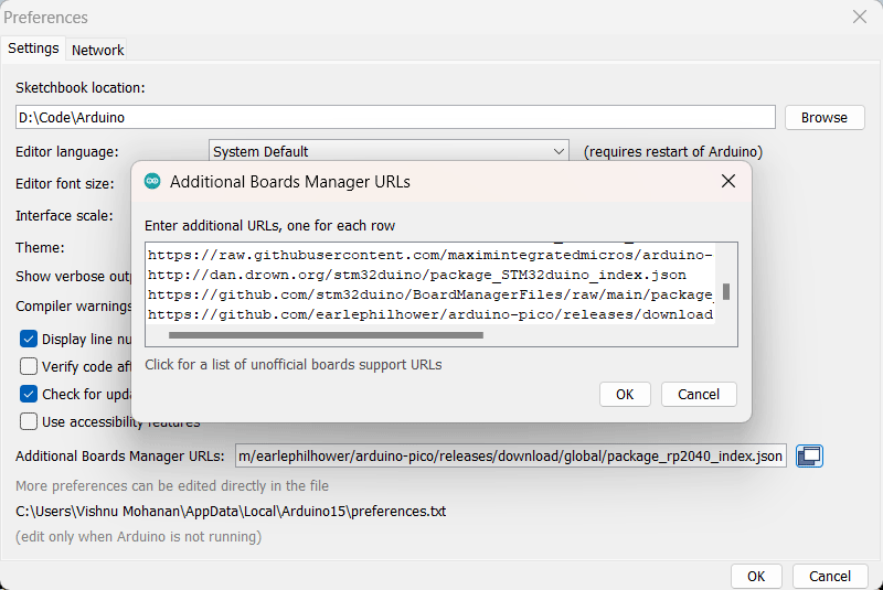
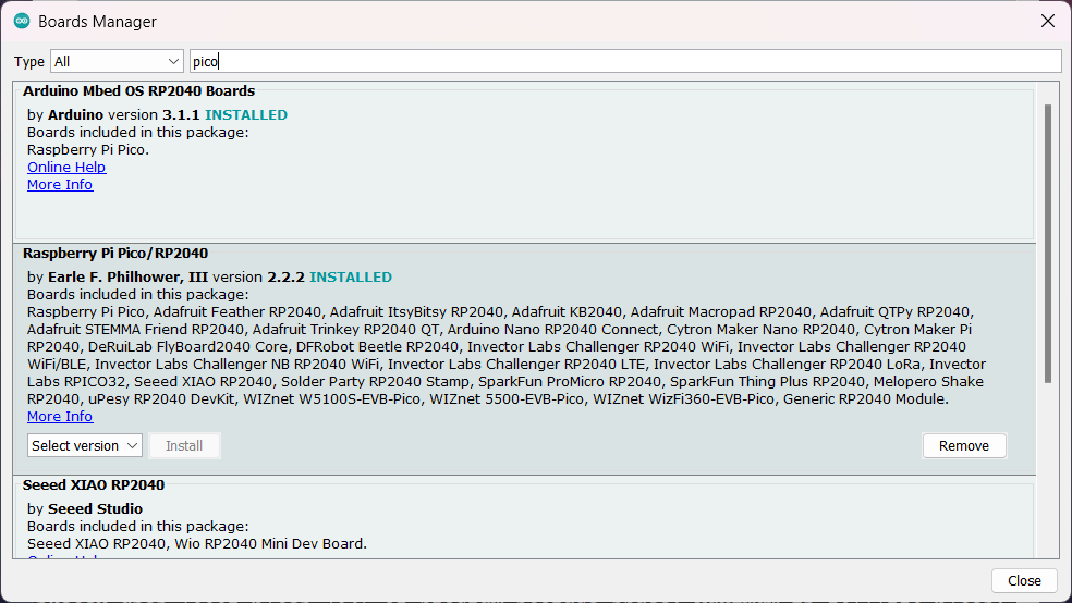
Now you can search for “pico” in the Boards Manager and install the latest package for Raspberry Pi Pico/RP2040.
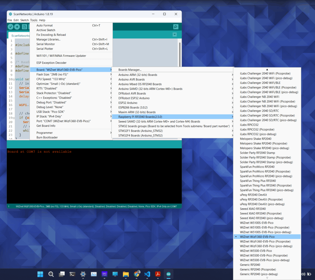
You can select the WIZnet WizFi360-EV-Pico board from the Tools menu. As you can see, there is a large list of supported boards. Now try opening the basic blink sketch from File → Examples → 01.Basics → Blink. Then select the port and upload the code. The LED on your board should be blinking.
In case you can not find any COM ports associated with the board, then simply press and release the RESET button while holding the BOOTSEL button. This will force the board to initialize as a mass-storage device. Arduino IDE will be then able to find your board and upload the code. From there on, you don’t need to press any buttons. The IDE will automatically reinitialize the board just before uploading the code. You will also be able to see the new COM port.
WizFi360 Arduino Library
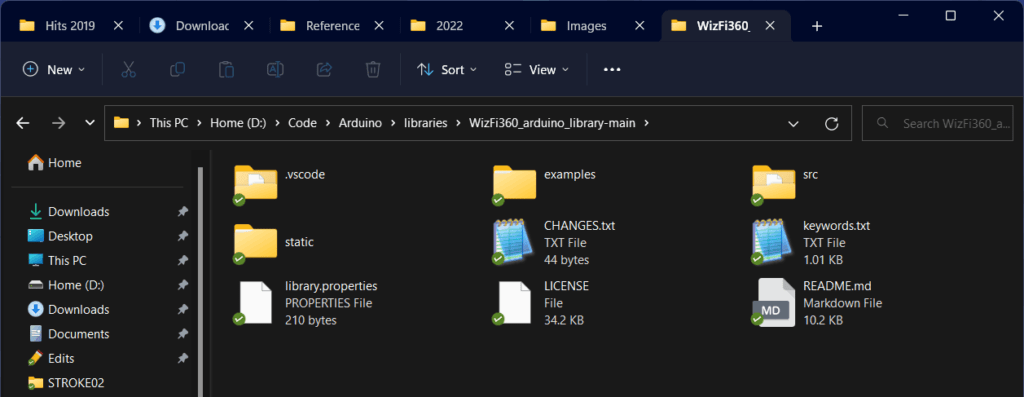
WIZnet has provided an Arduino library to communicate with the WizFi360 module and a few example sketches that implement basic Wi-Fi applications. You can install the WizFi360 library by downloading it as a ZIP file and adding it to your Arduino libraries folder. Unfortunately, the library is not published yet on the official library list and therefore you can not find it on the Arduino Library Manager.
But if you search for “wizfi” you will be able to find another library published by JongHyun Woo which is meant for a WizFi360-PA-based board called OrangeBoard WiFi. It also has similar examples but lacks any documentation. So don’t install that.
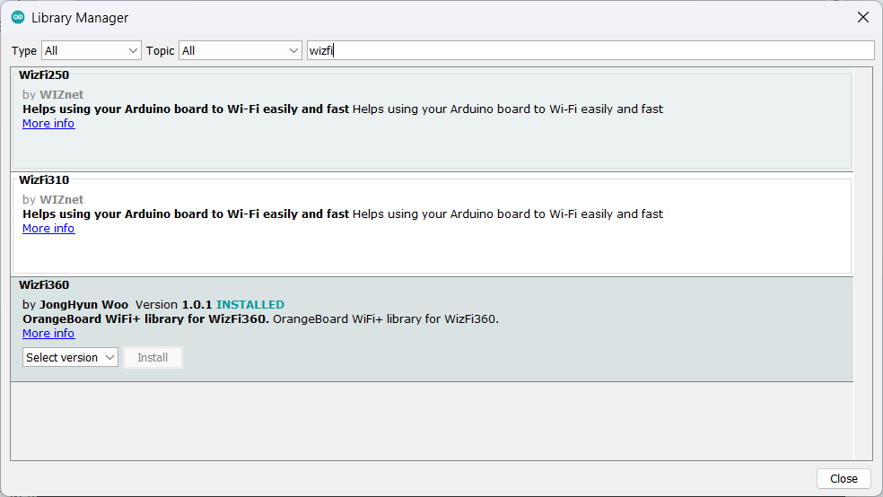
The official WizFi360 library is actually a fork of the WiFiEsp library originally developed for ESP8266 AT firmware. The following examples are available in the official WizFi360 library.
- ConnectWPA
- ScanNetworks
- Thingspeak
- UdpNTPClient
- UdpSendReceive
- WebClient
- WebClientRepeating
- WebClientSSL
- WebServer
- WebServerAP
- WebServerLed
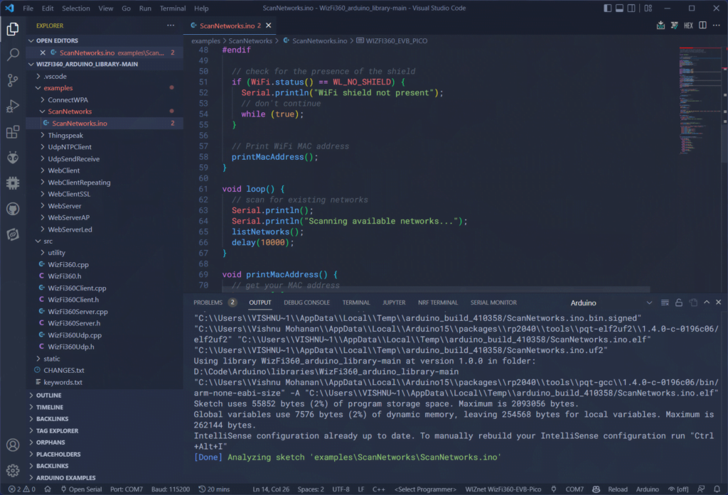
The examples can be directly run on both WizFi360-EVB-Pico and an Arduino Mega connected to WizFi360-EVB-Shield. You can adapt these examples for any other boards as well. You can select the target board by commenting or uncommenting either one of WIZFI360_EVB_PICO or ARDUINO_MEGA_2560 lines. Below is a screenshot of the ScanNetworks example showing the list of detected networks.
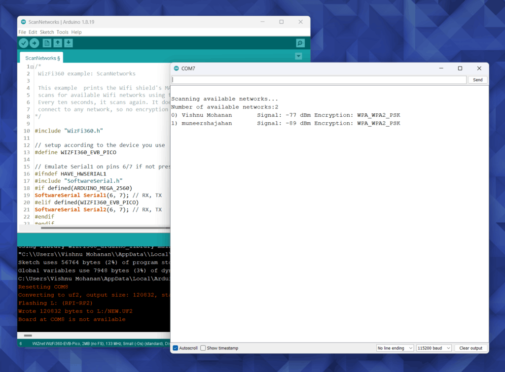
You can run these examples from Visual Studio Code (VS Code) also. We have a detailed tutorial on developing Arduino projects with the powerful VS Code IDE.
How to Use VS Code for Creating and Uploading Arduino Sketches
AT Command Testing with Serial Pass-Through
The official examples don’t reveal much about how the communication between the RP2040 and WizFi360 Wi-Fi module takes place. To see that, we can directly talk to the WizFi360 module with the help of AT commands sent from the serial monitor. For this, we will use the RP2040 as a serial pass-through (USB-to-Serial) device that will accept the AT commands from the serial terminal and send them to the Wi-Fi module. Any output from the Wi-Fi module will be sent to the serial monitor through the same RP2040.
Try uploading the following code and opening the serial monitor in Arduino IDE. This sketch can verify if your Wi-Fi module is working fine.
#include "WizFi360.h"

#define WIZFI360_EVB_PICO

//Baudrate
#define SERIAL_BAUDRATE   115200
#define SERIAL2_BAUDRATE  115200

void setup() {
  // initialize serial for debugging
  Serial.begin (SERIAL_BAUDRATE);
  Serial2.begin (SERIAL2_BAUDRATE);
  delay (2000);

  WiFi.init (&Serial2);

  // check for the presence of the module
  if (WiFi.status() == WL_NO_SHIELD) {
    Serial.println ("WiFi module is not present");
    // don't continue
    while (true);
  }
}

void loop() {
  if (Serial.available() > 0) {
    String inputString = Serial.readString();
    Serial.print (inputString);
    delay (10);
    Serial2.print (inputString);
    delay (100);
  }

  if (Serial2.available() > 0) {
    String inputString = Serial2.readString();
    Serial.println (inputString);
  }
}
We are initializing both the USB serial and UART serial with a baudrate of 115200. Then we can check the presence of the Wi-Fi module just to make sure it is in working mode. In the loop() we will accept any inputs from the serial monitor and send them directly to the UART port to which the Wi-Fi module is connected. Valid AT commands will be executed by the module and we will see return messages in the serial monitor.
When sending the commands from the serial monitor, you must set the line ending to be Both NL & CR or they must be sent from RP2040. This ensures that the command strings are properly terminated. Shown below are the responses from the Wi-Fi module. The command AT just verifies the communication link. It should return OK in reply if everything is working correctly.
We also tried toggling the GPIO pin connected to the blue LED on the module and it worked. You can find the complete set of AT commands here.
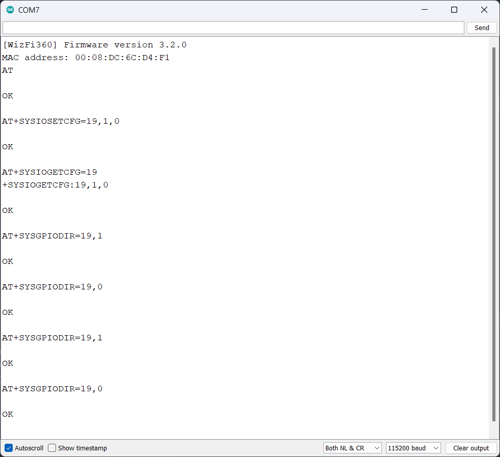
[WizFi360] Firmware version 3.2.0

AT

OK

AT+SYSIOSETCFG=19,1,0

OK

AT+SYSIOGETCFG=19
+SYSIOGETCFG:19,1,0

OK

AT+SYSGPIODIR=19,1

OK

AT+SYSGPIODIR=19,0

OK

AT+SYSGPIODIR=19,1

OK

AT+SYSGPIODIR=19,0

OK
C/C++ Projects with Pico SDK and VS Code
Another way of developing applications is by using the official SDK available for WizFi360 boards. It is not a complete SDK with APIs. Instead, it is more a wrapper that implements AT command-based functions using a CMSIS-compliant structure using many additional libraries. This allows the project to be compiled in all ARM-compatible development environments. It still uses the Pico-SDK for compiling code for RP2040. The main libraries and SDKs are,
- CMSIS_5 – this is a set of tools, APIs, frameworks, and workflows that help to simplify software reuse, reduce the learning curve for microcontroller developers, speed-up project build and debugging, and thus reduce the time to market for new applications.
- CMSIS-Driver – this contains MCU independent device driver implementations and template files for ARM controllers.
- CMSIS-FreeRTOS – this is a common API for embedded microcontroller real-time operating system FreeRTOS.
- IoT_Socket – this contains the code of IoT Socket – a simple BSD-like IP socket interface that implements the glue logic between IoT cloud connectors (IoT clients) and the underlying communication stack.
- mbedtls – this is a widely used library that supports additional algorithms and support related to TLS and SSL connections.
- pico-sdk – the official Pico C/C++ SDK.
- pico-extras – this has additional libraries that are not yet ready for inclusion in the Pico SDK proper, or are just useful but don’t necessarily belong in the Pico SDK.
To run the examples for WizFi360-EVB-Pico, clone this repository on your machine. To compile the example projects, you must have completed setting up a C/C++ build environment for the Pico-SDK. We have a detailed tutorial available for doing the same. This tutorial applies to all C/C++ projects that make use of the official Pico-SDK on a Windows computer.
How to Create A Standalone Raspberry Pi Pico C/C++ Project in Windows and Build from Command-Line and VS Code
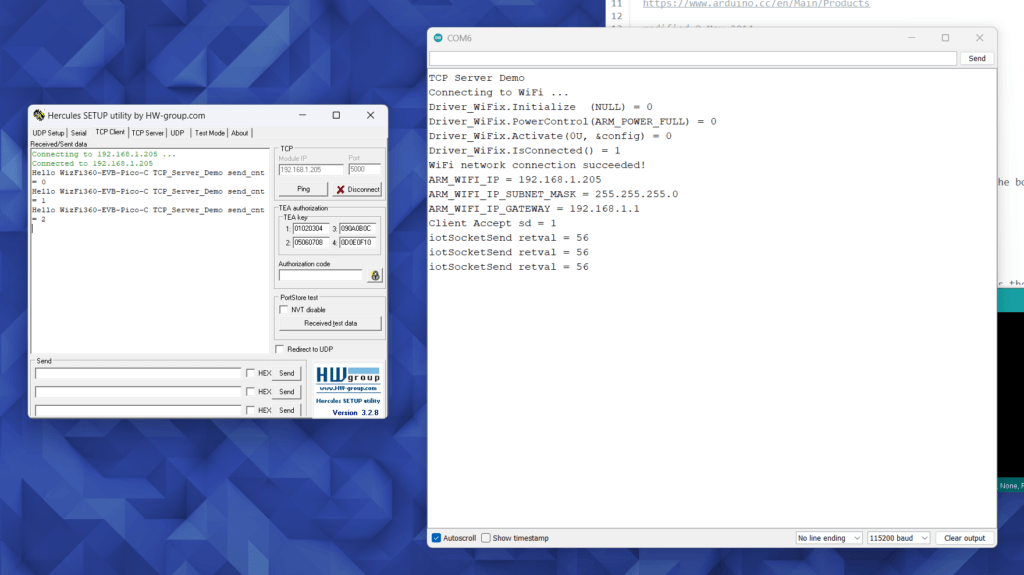
Let’s compile and run the TCP Server Demo example. This project allows the WizFi360 to connect to an existing Wi-Fi network and open a TCP socket to it. We can then use clients like the Hercules Setup Utility to connect to this port and exchange data. You can find details for configuring the project before compiling can be found here.
You can add the Wi-Fi network name and password to the socket_startup.c file inside the example folder. It is one of the four .c files associated with the project.
- app_main.c – where your main function and threads are at. This determines the program flow.
- socket_startup.c – this takes care of connecting to the Wi-Fi network and obtaining the IP. It uses the CMSIS Wi-Fi Driver.
- iot_demo.c – this takes care of creating TCP sockets and sending and receiving data through it. It makes use of the IoT Socket API pack.
- tcp_server_demo.c – this initializes the RP2040 microcontroller clock and the FreeRTOS kernel. CMSIS-RTOS2 driver is used to wrap FreeRTOS.
Since there is no automatic programming option, you need to manually drag and drop the UF2 file from the build directory to your WizFi360-EVB-Pico board connected as a mass storage device. Below is the message printed by the board to the serial monitor.
TCP Server Demo
Connecting to WiFi ...
Driver_WiFix.Initialize  (NULL) = 0
Driver_WiFix.PowerControl(ARM_POWER_FULL) = 0
Driver_WiFix.Activate(0U, &config) = 0
Driver_WiFix.IsConnected() = 1
WiFi network connection succeeded!
ARM_WIFI_IP = 192.168.1.205
ARM_WIFI_IP_SUBNET_MASK = 255.255.255.0
ARM_WIFI_IP_GATEWAY = 192.168.1.1
There are two more examples SSL_Client_Demo and TCP_Client_Demo. In addition to these, there are examples that show connecting to AWS and Azure cloud platforms.
Debugging
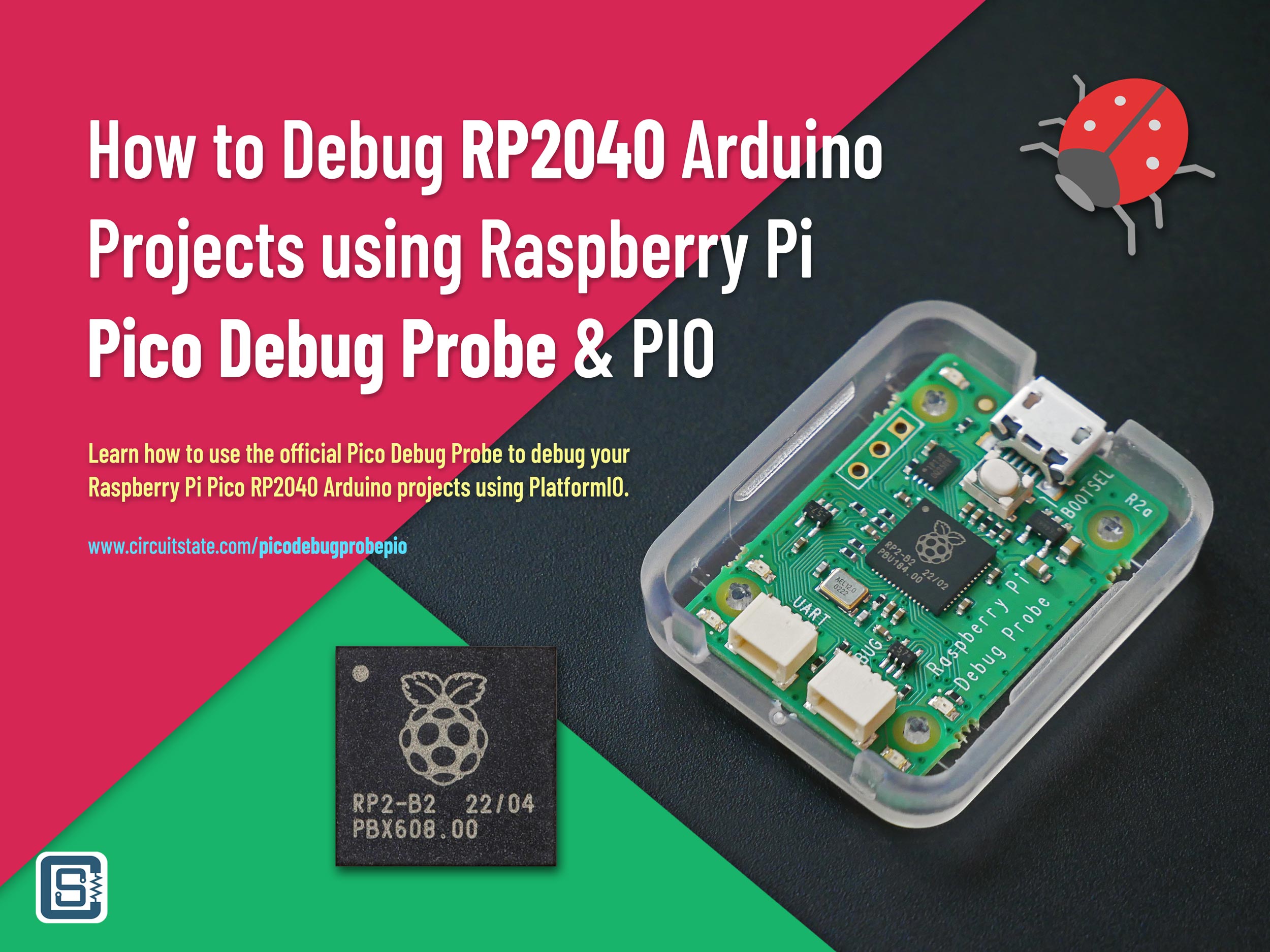
You can debug your WizFi360-EVB-Pico boards using the official Pico Debug Probe or another Raspberry Pi Pico running the Picoprobe firmware. We have debugging tutorials for RP2040 Arduino projects as well as Pico C/C++ SDK projects.
How to Debug RP2040 Arduino Projects Using Raspberry Pi Debug Probe & PlatformIO
Debugging RP2040 Pico C/C++ SDK Projects using Raspberry Pi Debug Probe & VS Code
With that, we think we have explained and included enough details to get started with your WizFi360-EVB-Pico board. We will be publishing more application-specific tutorials in the upcoming posts. Let us know your feedback on this article. Good luck with the competition.
Links
- WizFi360-EVB-Pico – Official Wiki Page
- Winnermicro W600 – Product Page
- W600 Datasheet – PDF
- WizFi360 Datasheet – PDF
- WizFi360 AT Instruction Set – PDF
- WizFi360 Hardware Design Guide – PDF
- WizFi360-EVB-Pico – Hardware Design Files
- WIZnet IoT Design Competition
- WIZnet India Website and Store
- Arduino Pico Core for RP2040
- Official WizFi360 Library for Arduino
- WizFi360-EVB-Pico-C – C/C++ Examples
- How to use VS Code for Creating and Uploading Arduino Sketches – Tutorial
- How to Create A Standalone Raspberry Pi Pico C/C++ Project in Windows and Build from Command-Line and VS Code
- Hercules Setup Utility
Short Link
- Short URL to this page – https//circuitstate.com/gswizpico







Great tutorial.
The
getIpAddress()is not working with the arduino-pico over version 2.3.0.Please use a branch WizFi360-EVB-Pico of WizFi360_arduino_library.
Thanks, Taylor for the feedback and tip 🙂