Getting Started with Arduino Nano ESP32 Wi-Fi & IoT Development Board
Get started with the latest Arduino Nano ESP32-S3 microcontroller board for Wi-Fi, BLE and IoT development board.
Arduinos and ESP32s have been around for a long time now. Arduino came first with their AVR-based microcontroller boards, targeting hobbyists, artists, and students. More Arduino boards with niche features were released in the years after the introduction of the Arduino Uno board. The ESP32 is younger than its sibling, the ESP8266, and both Wi-Fi microcontrollers (SoCs to be specific) are manufactured by the Chinese firm Espressif. The company was quick and dedicated to getting their products compatible with the already-popular Arduino development framework, by supporting their products with the official development of open-source Arduino cores (SDKs and toolchains). The effect of this was both the official Arduino boards and ESP boards have progressed parallelly as two streams over the years with continuous improvements to their supported software frameworks and tools. Even though Arduino was keen to use modern microcontrollers other than AVR on their boards, they never released a board with an ESP as the native chip. That changed when Arduino released its first development board with ESP32, the Arduino Nano ESP32. Since Arduino users are already familiar with many variants of the ESP32 chip, finding a new Arduino board with ESP32 on it will never feel anything fresh, and that’s a good thing. There is a massive user base around ESP32 microcontroller and so many things are already tried and fixed. You can find pretty much any info about ESP32 on the internet, whether it is about fixing some issue or interfacing a new sensor with it. In this post, we are going to find out everything about the new Arduino Nano ESP32 board and what it makes a great choice for your next IoT project.
We can develop embedded firmware for you
CIRCUITSTATE can develop embedded firmware for any microcontroller/microprocessor including 8051, PIC, AVR, ARM, STM32, ESP32, and RISC-V using industry-leading SDKs, frameworks, and tools. Contact us today to share your requirements.

Arduino Nano ESP32
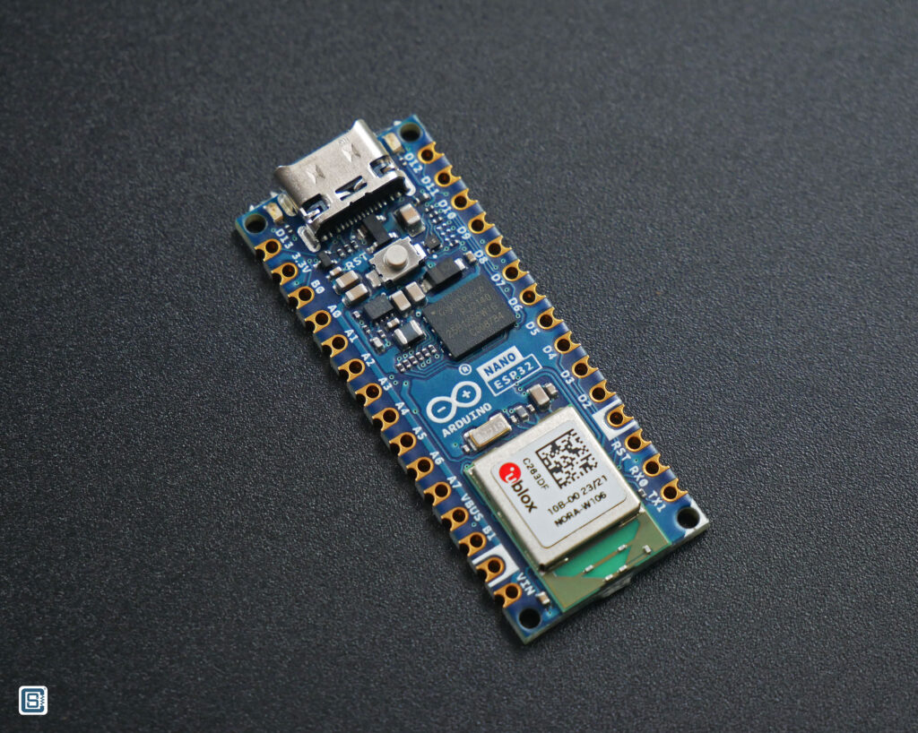
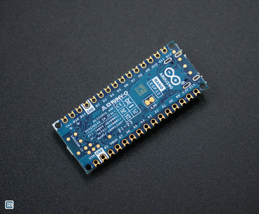
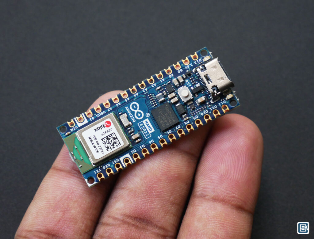
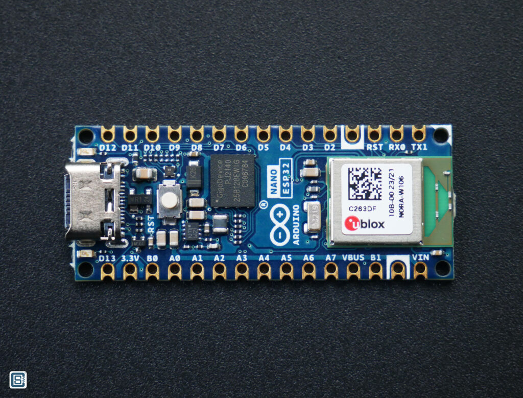
The Arduino Nano ESP32 has the form factor of the legacy Arduino Nano, but with two rows of castellated pins than regular through-hole pins. It allows the board to be mounted as an SMT module on a carrier PCB. Since there are no components on the back side of the board, you can incorporate the board directly on a product PCB if you want. The Nano ESP32 also has a USB-C connector instead of the old USB-Micro connector. This is also the first Nano form-factor board from Arduino with a USB-C connector. Hope Arduino uses USB-C connectors for all upcoming boards. Just like other Nano siblings, the Nano ESP32 is small and breadboard-compatible which makes it extremely easy for prototyping. You just need to solder two rows of header pins to do that.
The ESP32 chip used in the Nano ESP32 is the ESP32-S3R8 variant and it is integrated as a NORA-W106-10B module from u-blox. The 10B version of NORA-W106 has 8 MB of flash and 8 MB of PSRAM integrated into the module. So you get the best out of it. This is not the first time Arduino has used ESP32 modules from u-blox. For example, the Arduino Nano 33 IoT board had the ATSAMD21G18A-U as the main processor and u-blox NINA-W102 only for Wi-Fi connectivity. NORA-W106-10B integrates an ESP32-S3 chip which is an improved version of the older ESP32 chip. The module is much smaller than the official ESP32-S3 modules.
The Nano ESP32 incorporates 3 LEDs; a green one for power, an orange one for debugging, and an RGB LED for general-purpose use. A single push-button is available for resetting the board. There is no BOOT button, unlike other boards. Instead, you can double-press the RST button to enter the boot mode. The USB-C connector is directly connected to the native USB port of the ESP32-S3 full-speed USB peripheral. So programming, serial communication, and OTG functions can be implemented using the same port. Additionally, the USB port also supports JTAG through USB. So you can use the port for debugging also. We will see how you can use these features further below.
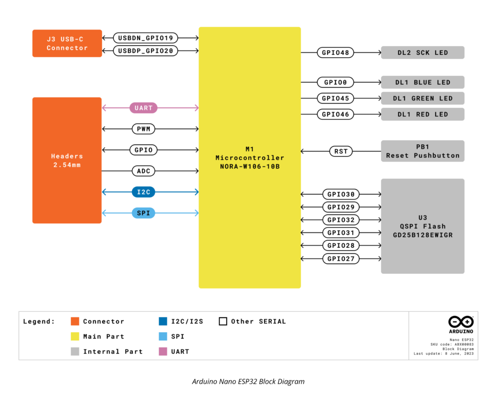
In terms of I/O, the Nano ESP32 breaks out 24 GPIO pins as pin headers. Some GPIO pins are reserved for exclusive functions such as USB, LED, external flash, etc. You can not use those pins as they are not broken out. Among the 24 GPIO pins, you will get 8 analog input pins through which you can measure voltages with 12-bit (4096 count) precision. A great feature of ESP32 microcontrollers is that their IO mux block can map peripheral functions to almost any GPIO pins. That means you are not limited to using specific pins for peripheral interfaces like UART or SPI. Instead, you can assign the GPIO pins in your code. PWM can be mapped into 8 GPIO pins max.
The ESP32-S3 uses a dual-core Xtensa LX7 processor which is an upgrade from the old LX6 CPU. The 240 MHz core clock allows you to crunch some pretty big numbers faster than an ordinary AVR microcontroller. To take advantage of that CPU power, you are also furnished with 384 KB ROM (not usable), 512 KB SRAM, 16 KB RTC SRAM, 8 MB flash (inside the module), 8 MB PSRAM (all integrated into the SoC), and 16 MB external flash memories. It is unlikely that you will ever run out of memories. The 384 KB ROM is used for storing the bootloader and other low-level hardware code permanently. You can not change the contents of it.
The Arduino Nano ESP32 can be powered from DC voltages from 6 to 21V, thanks to the MP2322GQH DC-DC step-down converter from Monolithic. It can supply a maximum continous current of 1A which is plenty for ESP32-based applications.
Below is a brief comparison between the board from the Arduino Nano family.
| Board | Nano | Nano Every | Nano 33 BLE | Nano 33 BLE Sense | Nano 33 IoT | Nano RP2040 Connect | Nano ESP32 |
|---|---|---|---|---|---|---|---|
| Processor | ATmega328P | ATmega4809 | nRF52840 | nRF52840 | SAMD21G18A | RP2040 | ESP32-S3 |
| Radio Module | x | x | NINA-B306 | NINA-B306 | NINA-W102 | NINA-W102 | NORA-W106-10B |
| Connectivity | x | x | Bluetooth | Bluetooth | Wi-Fi, Bluetooth | Wi-Fi, Bluetooth | Wi-Fi, Bluetooth |
| Clock Speed | 16 Mhz | 16 Mhz | 64 Mhz | 64 Mhz | 48 Mhz | 133 MHz | 240 MHz |
| Flash Memory | 32 KB | 48 KB | 256 KB | 256 KB | 264 KB | 16 MB | 16 MB |
| SRAM | 2 KB | 6 KB | 1 MB | 1 MB | 256 KB | 264 KB | 512 KB |
| EEPROM | 1 KB | 256 byte | x | x | x | x | |
| I/O Voltage | 5V | 5V | 3.3V | 3.3V | 3.3V | 3.3V | 3.3V |
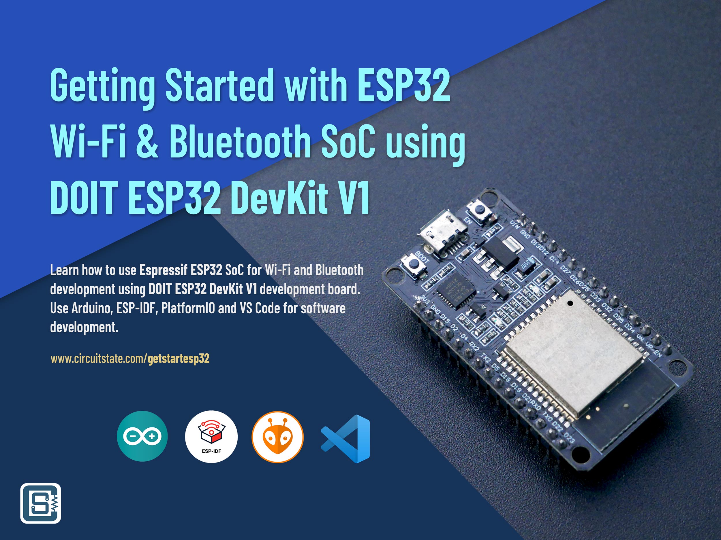
If you are new to ESP32 and don’t want to spend USD 20 on the official Arduino Nano ESP32, then you can get yourself a cheaper DOIT ESP32 DevKit V1 board and start developing your Wi-Fi and Bluetooth projects. We have a complete tutorial to get you started.
Getting Started with Espressif ESP32 Wi-Fi & Bluetooth SoC using DOIT-ESP32-DevKit-V1 Development Board
Specifications
| Board | Name | Arduino Nano ESP32 |
| SKU | ABX00092 | |
| Microcontroller | u-blox NORA-W106-10B (ESP32-S3R8) | |
| USB connector | USB-C | |
| Pins | Built-in LED Pin | 13 |
| Built-in RGB LED pins | 14-16 | |
| Digital I/O Pins | 14 | |
| Analog input pins | 8 | |
| PWM pins | 5 | |
| External interrupts | All digital pins | |
| Connectivity | Wi-Fi | IEEE 802.11b/g/n-compliant |
| Bluetooth | Bluetooth LE: Bluetooth 5, Bluetooth mesh | |
| Communication | UART | 2x |
| I2C | 1x, A4 (SDA), A5 (SCL) | |
| SPI | D11 (COPI), D12 (CIPO), D13 (SCK). Use any GPIO for Chip Select (CS) | |
| Power | I/O Voltage | 3.3 V |
| Input voltage (nominal) | 6-21 V | |
| Source Current per I/O Pin | 40 mA | |
| Sink Current per I/O Pin | 28 mA | |
| Clock speed | Processor | up to 240 MHz |
| Memory | ROM | 384 kB |
| SRAM | 512 kB | |
| External Flash | 16 MB | |
| Internal Flash | 8 MB | |
| PSRAM | 8 MB | |
| Dimensions | Width | 18 mm |
| Length | 45 mm | |
Pinout
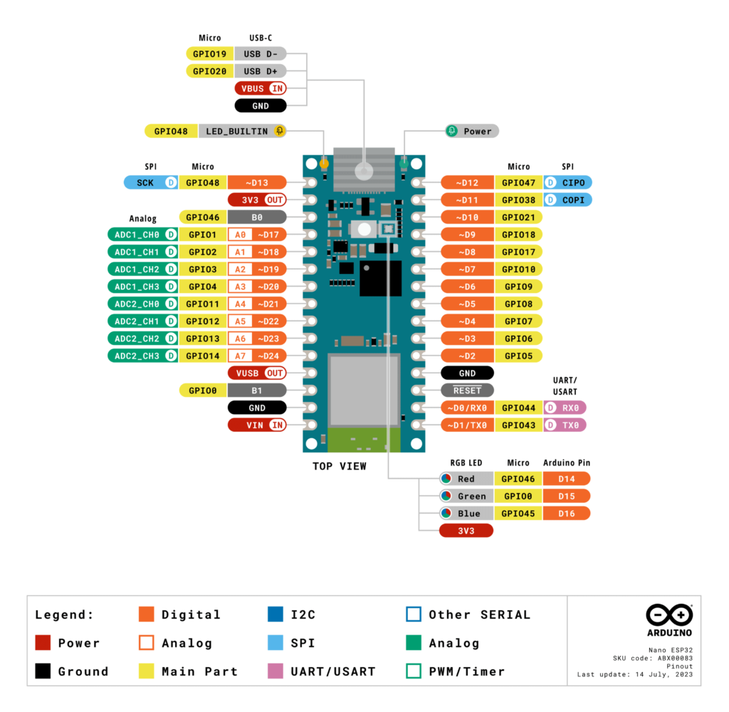
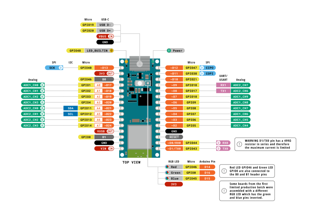
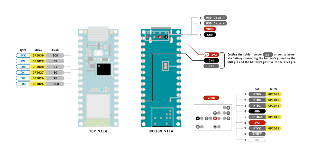
You can find the complete pinout of the Arduino Nano ESP32 on the Arduino resource page.
Schematic
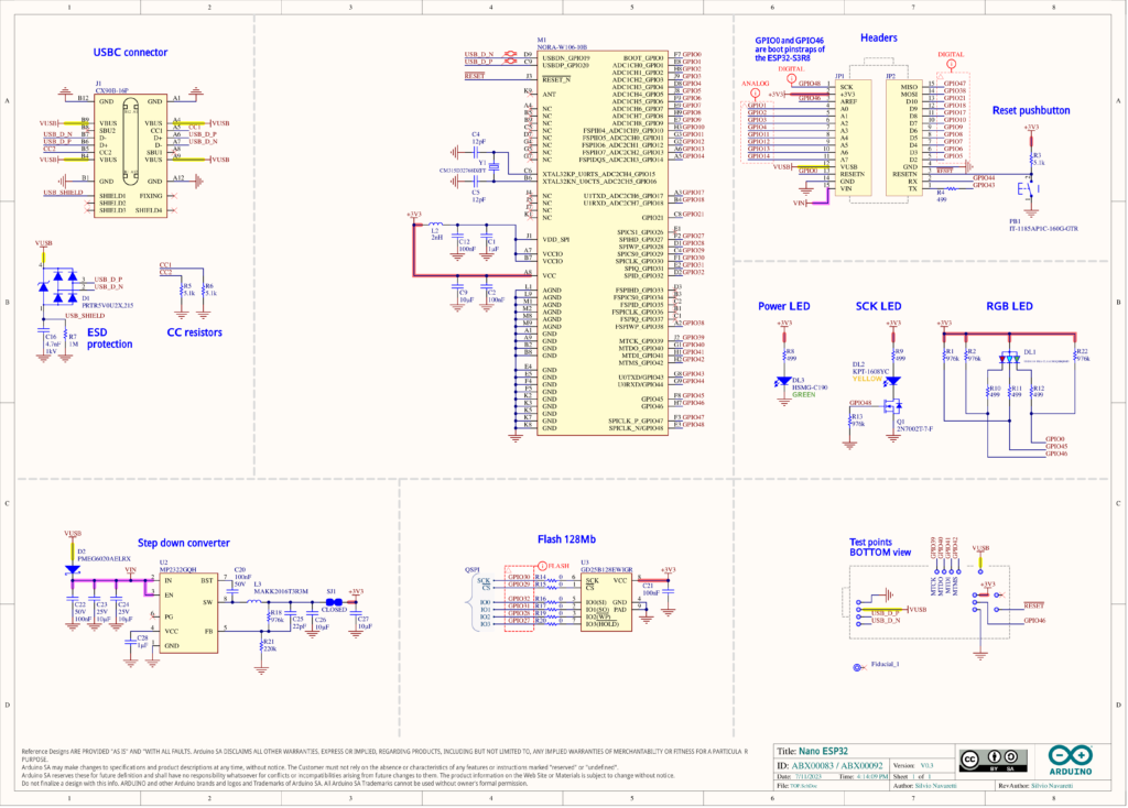
The schematic and PCB of Arduino Nano ESP32 are designed using Altium Designer. You can download the schematic files as PDF files or as original design files from the Arduino resources page.
Mechanical Drawing
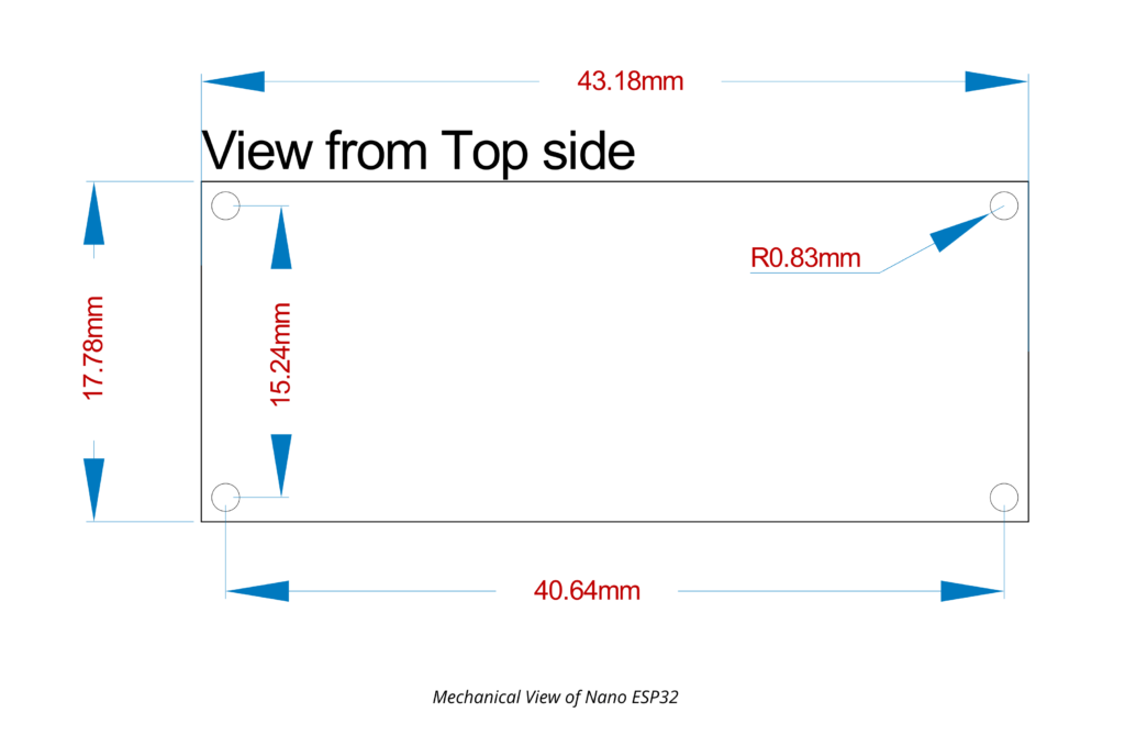
The mechanical design of all boards from the Nano family is the same.
u-blox NORA-W106-10B
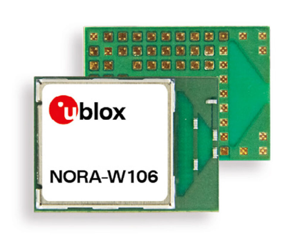
u-blox produces some of the best GNSS and connectivity modules in the world. Their NINA and NORA are no exceptions. The NINA/NORA series Wi-Fi and Bluetooth modules are probably one of the smallest System-on-Modules you can find on the market. This is true for the ESP32-based modules. We don’t know how they do it, but u-blox ESP32 modules are much smaller than the official ESP32 modules. Maybe they are using the WLCSP package or some other magic? Unfortunately, we never decapped any u-blox modules since none of the modules ever failed. Let us know if you know how they pulled it off.
NORA-W106-10B is the fully-featured module among the three. The other two are NORA-W101-00B with an antenna pin, and NORA-W106-00B with a PCB antenna. The only difference between NORA-W106-00B and NORA-W106-10B is the presence of 8 MB PSRAM on the latter. NORA-W106-10B uses the ESP32-S3R8 variant from the S3 family. NORA-W106-10B integrates all electrical pins on the underside of the module. So it will be challenging to hand-solder than the regular ESP32 modules. If you plan to buy the module, it costs around INR 690 on Mouser.
Specifications
| Specification | Value | |
|---|---|---|
| Bluetooth qualifications | v5.0 (Bluetooth Low Energy) | |
| Chip inside | ESP32-S3 (ESP32-S3R8) | |
| Bluetooth output power EIRP | 8 dBm | |
| Wi-Fi output power EIRP | 18 dBm | |
| Maximum Wi-Fi range | 500 m | |
| Wi-Fi frequency | 2.4 GHz | |
| Wi-Fi standards (IEEE 802.11) | IEEE 802.11b, IEEE 802.11g, IEEE 802.11n | |
| Max Wi-Fi data rate | 150 Mbps | |
| MCU | Xtensa LX7, 240 MHz dual-core | |
| RAM | 512 kB | |
| Flash | 8192 kB (8 MB) | |
| PSRAM | 8 MB | |
| UART | 3 | |
| USB | 1 | |
| GPIO | 38 | |
| ADC Resolution | 12 bit | |
| I2S | 2 | |
| SPI | 4 | |
| TWI (I2C compatible) | 2 | |
| TWAI (CAN 2.0) | 1 | |
| PWM | 1 block (8 channels) | |
| Maximum supply | 3.6 V | |
| Nominal supply | 3.3 V | |
| Minimum supply | 3 V | |
| Maximum temperature | 85 °C | |
| Minimum temperature | -40 °C | |
| Bluetooth mesh ready | ✓ | |
| Point-to-point protocol (PPP) | ✓ | |
| Secure boot ready | ✓ | |
| Simultaneous GATT server and client | ✓ | |
| Wi-Fi enterprise security | ✓ | |
| WPA3 | ✓ | |
| Approvals | Europe (ETSI RED), United Kingdom (UKCA), US (FCC/CFR 47 part 15 unlicensed modular transmitter approval), Canada (IC RSS), Japan (MIC), Taiwan (NCC) 1, South Korea (KCC) , Australia (ACMA), New Zealand, Brazil (Anatel) 1, South Africa (ICASA) | |
| Antennas | Embedded PCB antenna | |
| Dimensions | 10.4 x 14.3 x 1.8 mm | |
Pinout
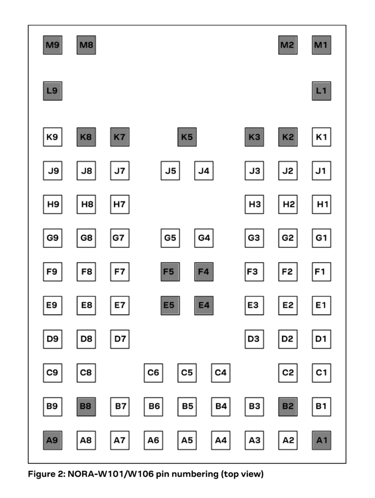
ESP32-S3
ESP32-S3 is a more recent variant from the ESP32 family. The first ESP32 was simply called “ESP32” without any prefix or suffix to the family name. But the term ESP32 is also used for talking about the ESP32 family of SoCs and modules. So if you see the term ESP32, it could mean the ESP32 family, or the first version of the chip. The ESP32 family chips fall in the SoC (System-on-Chip) category rather than plain microcontrollers, due to the heavy integration of a multitude of peripherals inside a single chip die. We are talking about RF front-ends, memories, multiple CPUs, and so on. Below is a list of all SoC variants in the ESP family from Espressif.
| SoC Family | CPU | Core Count | Frequency | Bluetooth | WiFi |
|---|---|---|---|---|---|
| ESP8266EX | Xtensa 32-bit L106 | 1 | 160 MHz | N/A | IEEE 802.11 b/g/n; 2.4 GHz; HT20; up to 75 Mbps |
| ESP8285 | Xtensa 32-bit L106 | 1 | 160 MHz | N/A | IEEE 802.11 b/g/n; 2.4 GHz; HT20; up to 75 Mbps |
| ESP32 | Xtensa 32-bit LX6 CPU | 2 | 240 MHz | BR/EDR + Bluetooth LE v4.2 | IEEE 802.11 b/g/n; 2.4 GHz; HT20/40; up to 150 Mbps |
| ESP32-S2 | Xtensa 32-bit LX7 | 1 | 240 MHz | N/A | IEEE 802.11 b/g/n; 2.4 GHz; HT20/40; up to 150 Mbps |
| ESP32-C3/ESP8685 | 32-bit RISC-V | 1 | 160 MHz | Bluetooth LE v5.0 | IEEE 802.11 b/g/n; 2.4 GHz; HT20/40; up to 150 Mbps |
| ESP32-S3 | Xtensa 32-bit LX7 | 2 | 240 MHz | Bluetooth LE v5.0 | IEEE 802.11 b/g/n; 2.4 GHz; HT20/40; up to 150 Mbps |
| ESP32-C2/ESP8684 | 32-bit RISC-V | 1 | 120 MHz | Bluetooth LE v5.0 | IEEE 802.11 b/g/n; 2.4 GHz; HT20; up to 150 Mbps |
| ESP32-C6 | 32-bit RISC-V | 1 | 160 MHz | Bluetooth LE v5.3 | IEEE 802.11 b/g/n; 2.4 GHz; HT20/40; up to 150 Mbps |
| ESP32-H2 | 32-bit RISC-V | 1 | 96 MHz | Bluetooth LE v5.0 | N/A |
You can check out the ESP Product Selector to learn more about the different types of ESP32 SoCs and their features. In addition to different subfamilies of SoCs, each SoC also has different variants based on some feature variations. For example, the ESP32-S3 has 6 variants.
| Ordering Code | In-Package Flash | In-Package PSRAM | Ambient Temp (°C) | VDD_SPI Voltage |
|---|---|---|---|---|
| ESP32-S3 | – | – | -40 ~ 105 | 3.3 V/1.8 V |
| ESP32-S3FN8 | 8 MB (Quad SPI)4 | – | -40 ~ 85 | 3.3 V |
| ESP32-S3R2 | – | 2 MB (Quad SPI) | -40 ~ 85 | 3.3 V |
| ESP32-S3R8 | – | 8 MB (Octal SPI) | -40 ~ 65 | 3.3 V |
| ESP32-S3R8V | – | 8 MB (Octal SPI) | -40 ~ 65 | 1.8 V |
| ESP32-S3FH4R2 | 4 MB (Quad SPI) | 2 MB (Quad SPI) | -40 ~ 85 | 3.3 V |
NORA-W106-10B uses the ESP32-S3R8 variant that comes with 8 MB PSRAM in the die but has no flash capacities. Arduino Nano ESP32 stores your program inside the external 16 MB (128 Mb) flash chip. ESP32-S3 is a dual-core 32-bit Xtensa LX7 CPU with an additional low-power core (ULP). The Xtensa is a standalone RISC IP from Tensilica (now owned by Cadence).
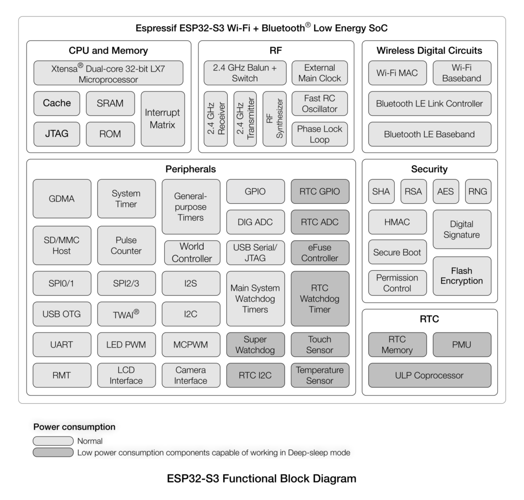
Features & Specifications
- Wi-Fi
- IEEE 802.11b/g/n-compliant
- Supports 20 MHz, 40 MHz bandwidth in 2.4 GHz band
- 1T1R mode with data rate up to 150 Mbps
- Wi-Fi Multimedia (WMM)
- TX/RX A-MPDU, TX/RX A-MSDU
- Immediate Block ACK
- Fragmentation and defragmentation
- Automatic Beacon monitoring (hardware TSF)
- 4 × virtual Wi-Fi interfaces
- Simultaneous support for Infrastructure BSS in Station, SoftAP, or Station + SoftAP modes Note that when ESP32-S3 scans in Station mode, the SoftAP channel will change along with the Station channel
- Antenna diversity
- 802.11mc FTM
- Bluetooth
- Bluetooth LE: Bluetooth 5, Bluetooth mesh
- High power mode (20 dBm)
- Speed: 125 Kbps, 500 Kbps, 1 Mbps, 2 Mbps
- Advertising extensions
- Multiple advertisement sets
- Channel selection algorithm #2
- Internal co-existence mechanism between Wi-Fi and Bluetooth to share the same antenna
- CPU and Memory
- Xtensa® dual-core 32-bit LX7 microprocessor, up to 240 MHz
- 128-bit data bus and SIMD commands
- 384 KB ROM
- 512 KB SRAM
- 16 KB SRAM in RTC
- SPI, Dual SPI, Quad SPI, Octal SPI, QPI and OPI interfaces that allow connection to multiple flash and external RAM
- Flash controller with cache is supported
- Flash In-Circuit Programming (ICP) is supported
- CoreMark® scores:
- 1 core at 240 MHz: 613.86 CoreMark; 2.56 CoreMark/MHz
- 2 cores at 240 MHz: 1181.60 CoreMark; 4.92 CoreMark/MHz
- Advanced Peripheral Interfaces
- 45 × programmable GPIOs
- Digital interfaces:
- 4 × SPI
- 1 × LCD interface (8-bit ~16-bit parallel
- RGB, I8080 and MOTO6800), supporting conversion between RGB565, YUV422, YUV420 and YUV411
- 1 × DVP 8-bit ~16-bit camera interface
- 3 × UART
- 2 × I2C
- 2 × I2S
- 1 × RMT (TX/RX)
- 1 × pulse counter
- LED PWM controller, up to 8 channels
- 1 × full-speed USB OTG
- 1 × USB Serial/JTAG controller
- 2 × MCPWM
- 1 × SD/MMC host controller with 2 slots
- General DMA controller (GDMA), with 5 transmit channels and 5 receive channels
- 1 × TWAI controller, compatible with ISO
- 11898-1 (CAN Specification 2.0)
- Analog interfaces:
- 2 × 12-bit SAR ADCs, up to 20 channels
- 1 × temperature sensor
- 14 × touch-sensing IOs
- Timers:
- 4 × 54-bit general-purpose timers
- 1 × 52-bit system timer
- 3 × watchdog timers
- Low Power Management
- Power Management Unit with five power modes
- Ultra-Low-Power (ULP) coprocessors:
- ULP-RISC-V coprocessor
- ULP-FSM coprocessor
- Security
- Secure boot
- Flash encryption
- 4-Kbit OTP, up to 1792 bits for users
- Cryptographic hardware acceleration:
- AES-128/256 (FIPS PUB 197)
- Hash (FIPS PUB 180-4)
- RSA
- Random Number Generator (RNG)
- HMAC
- Digital signature
Pinout
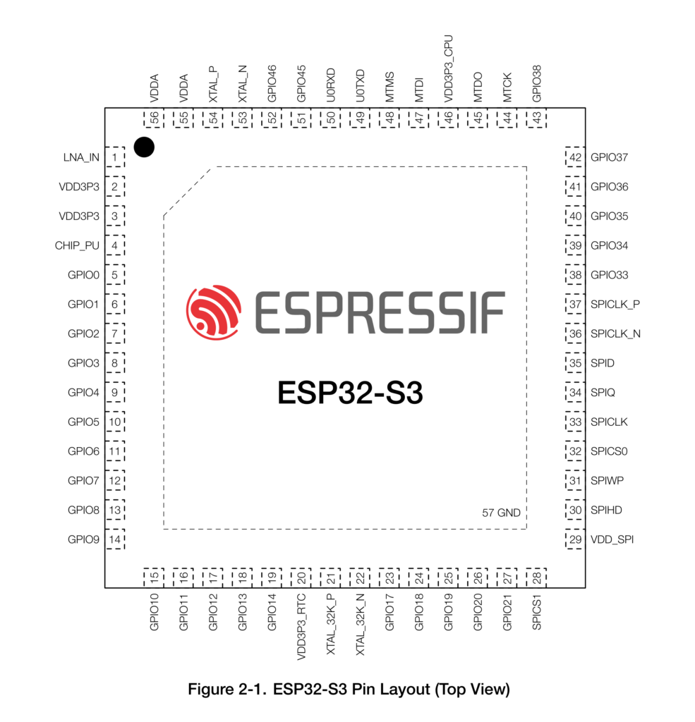
Programming
Programming the Arduino Nano ESP32 is as easy as any other ESP32 board. The serial bootloader inside the chip allows us to upload programs directly via USB. In the case of ESP32-S3, we will use the native USB port instead of an external USB-Serial chip. The board is officially supported by two frameworks; the official Arduino Development Framework (ADF) and the Espressif IoT Development Framework (ESP-IDF). For the ADF, there are two cores (a preconfigured SDK and toolchain set) available; Arduino ESP32 Boards from Arduino which is specifically configured only for official Arduino boards with ESP32s, and the arduino-esp32 Arduino core from Espressif, maintained by themselves. The core from Arduino is a fork of the Espressif project. So they are essentially the same.
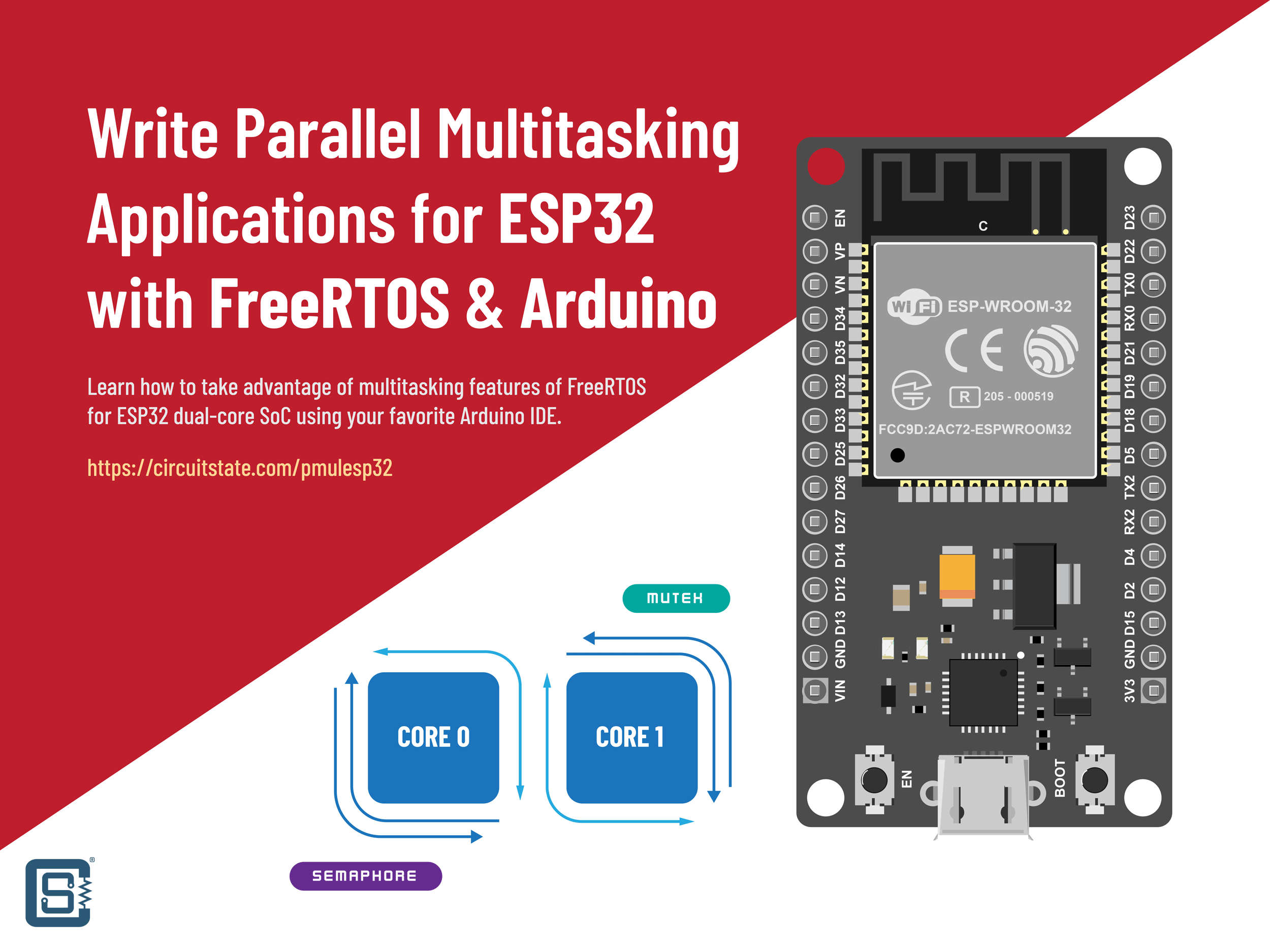
Despite which framework or IDEs you are using, projects for ESP32 are compiled by the ESP-IDF toolchain which is the fully-supported SDK for all ESP boards. FreeRTOS is used as the main RTOS of all projects which allows you to take advantage of the two cores and manage parallel multitasking. If you want to learn more about multitasking in ESP32 using FreeRTOS, we have a dedicated tutorial for it.
How to Write Parallel Multitasking Applications for ESP32 using FreeRTOS & Arduino
Arduino IDE
We will use the latest Arduino IDE 2 for all demonstrations in this tutorial. The version 2 supersedes the older version 1.8 and brings modern IDE features for Arduino development. If you are still using the older IDE, it is a good time to switch. You can download the IDE from the Arduino website and install it on your system if you haven’t already. After installing, open the Boards Manager from the left pane and search for “esp32”. You will see two or more results there. In our case, we see three of them. Install the esp32 by Espressif Systems if you want to compile for all ESP32-based boards. If you will only ever use the Arduino Nano ESP32, then you can install the Arduino ESP32 Boards by Arduino. We recommend installing both since you will also get ready-to-compile examples exclusive for Arduino Nano ESP32 when you install the official package.
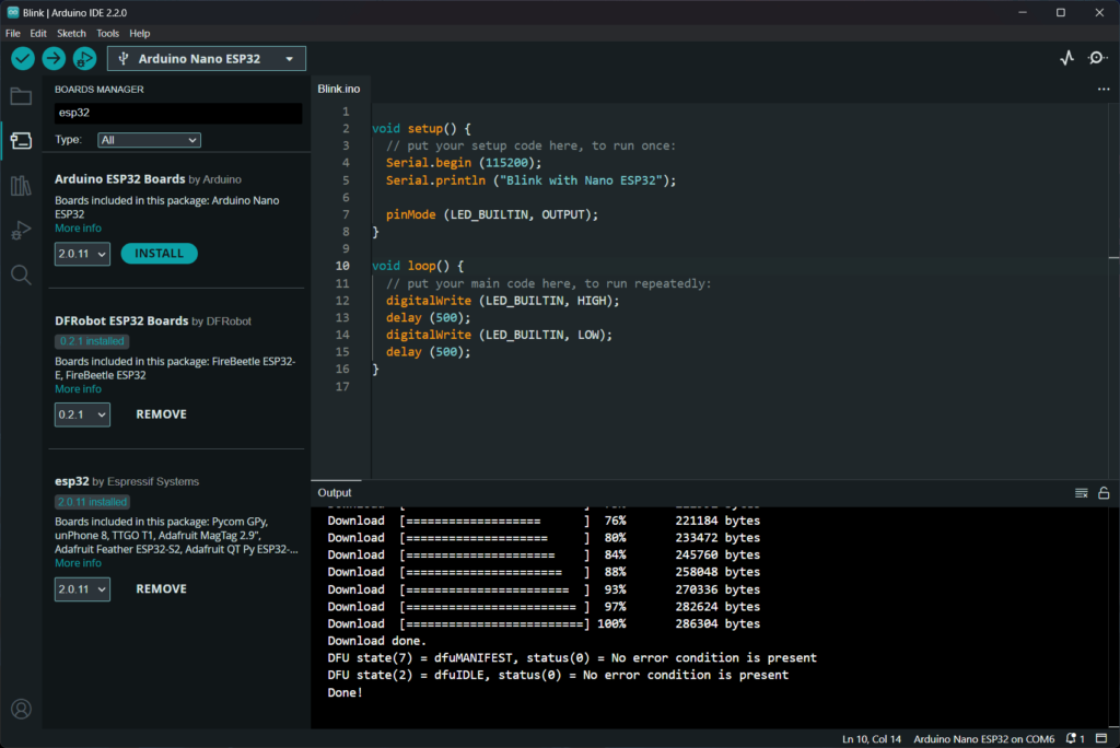
We have already installed version 2.0.11 of esp32 by Espressif and Arduino ESP32 Boards by Arduino at the time of writing this tutorial. Now if you connect the Arduino Nano ESP32 to your computer, you will get a single COM port created on your system, if you are on Windows. You can find the list of serial devices from the top bar or by going to Tools → Port. Then you can select the board with the name Arduino Nano ESP32 from the serial port list. In addition to the serial COM port, Arduino Nano ESP32 will also create a USB DFU (Device Firmware Upgrade) protocol port named Arduino DFU. You can see both ports by opening the serial port and devices list on Arduino IDE 2 as shown below.
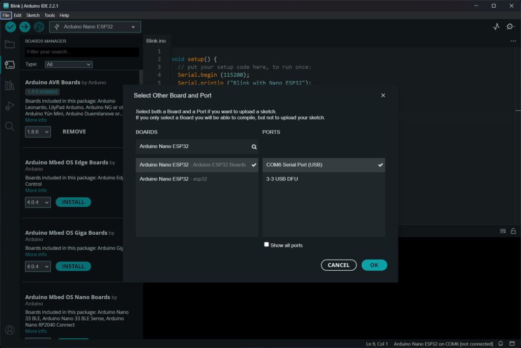
The Arduino IDE can detect which board you have connected and can recommend the supported packages based on it. You can select either of the packages to compile the code. You can also set the board type by going to Tools → Board. Now you are ready to compile the first sketch for Arduino Nano ESP32. You can perform compilation and uploading with a single click of the Upload button on the top bar. Below is a sample Blink sketch that will blink the on-board LED.
void setup() {
  // put your setup code here, to run once:
  Serial.begin (115200);
  Serial.println ("Blink with Nano ESP32");

  pinMode (LED_BUILTIN, OUTPUT);
}

void loop() {
  // put your main code here, to run repeatedly:
  digitalWrite (LED_BUILTIN, HIGH);
  delay (500);
  digitalWrite (LED_BUILTIN, LOW);
  delay (500);
}Compile the project by clicking the Verify button on the top left. The console output window will show the compilation log and below is a part of that.
"C:\\Users\\Vishnu Mohanan\\AppData\\Local\\Arduino15\\packages\\esp32\\tools\\xtensa-esp32s3-elf-gcc\\esp-2021r2-patch5-8.4.0/bin/xtensa-esp32s3-elf-size" -A "C:\\Users\\Vishnu Mohanan\\AppData\\Local\\Temp\\arduino\\sketches\\8DA72F1453A887AECAAF7F5938781341/Blink.ino.elf"
Sketch uses 285937 bytes (9%) of program storage space. Maximum is 3145728 bytes.
Global variables use 30732 bytes (9%) of dynamic memory, leaving 296948 bytes for local variables. Maximum is 327680 bytes.
"C:\Users\Vishnu Mohanan\AppData\Local\Arduino15\packages\arduino\tools\dfu-util\0.11.0-arduino5/dfu-util" --device 0x2341:0x0070 -D "C:\Users\Vishnu Mohanan\AppData\Local\Temp\arduino\sketches\8DA72F1453A887AECAAF7F5938781341/Blink.ino.bin" -Q
dfu-util 0.11-arduino4

Copyright 2005-2009 Weston Schmidt, Harald Welte and OpenMoko Inc.
Copyright 2010-2021 Tormod Volden and Stefan Schmidt
This program is Free Software and has ABSOLUTELY NO WARRANTY
Please report bugs to http://sourceforge.net/p/dfu-util/tickets/

Opening DFU capable USB device...
Device ID 2341:0070
Device DFU version 0101
Claiming USB DFU Interface...
Setting Alternate Interface #0 ...
Determining device status...
DFU state(2) = dfuIDLE, status(0) = No error condition is present
DFU mode device DFU version 0101
Device returned transfer size 4096
Copying data from PC to DFU device

Download	[                         ]   0%            0 bytes
Download	[=                        ]   4%        12288 bytes
Download	[==                       ]   8%        24576 bytes
Download	[===                      ]  12%        36864 bytes
Download	[====                     ]  16%        49152 bytes
Download	[=====                    ]  21%        61440 bytes
Download	[======                   ]  25%        73728 bytes
Download	[=======                  ]  28%        81920 bytes
Download	[========                 ]  32%        94208 bytes
Download	[=========                ]  36%       106496 bytes
Download	[==========               ]  40%       118784 bytes
Download	[===========              ]  45%       131072 bytes
Download	[===========              ]  47%       139264 bytes
Download	[============             ]  49%       143360 bytes
Download	[=============            ]  52%       151552 bytes
Download	[==============           ]  56%       163840 bytes
Download	[===============          ]  60%       176128 bytes
Download	[================         ]  64%       188416 bytes
Download	[=================        ]  69%       200704 bytes
Download	[==================       ]  73%       212992 bytes
Download	[===================      ]  76%       221184 bytes
Download	[====================     ]  80%       233472 bytes
Download	[=====================    ]  84%       245760 bytes
Download	[======================   ]  88%       258048 bytes
Download	[=======================  ]  93%       270336 bytes
Download	[======================== ]  97%       282624 bytes
Download	[=========================] 100%       286304 bytes
Download done.
DFU state(7) = dfuMANIFEST, status(0) = No error condition is present
DFU state(2) = dfuIDLE, status(0) = No error condition is present
Done!
After successfully uploading the code, the orange LED on your Arduino Nano ESP32 should blink every second.
VS Code + Arduino
If you are like us, you would prefer to use Visual Studio Code (VS Code) for everything. Developing projects for Arduino Nano ESP32 is much easier with a combination of VS Code and the Arduino extension. You need to install the Arduino CLI for this to work. If you are using the same configuration for Arduino IDE and Arduino CLI, then installing the board packages has to be done only once. You can open your existing Arduino sketch (.ino files) folders in VS Code and the Arduino extension will detect your project. You need to select the board type and the serial port before compiling and uploading the code.
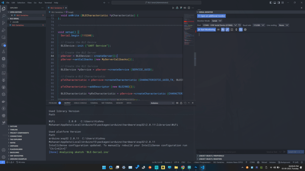
If you want to learn more about developing Arduino projects with VS Code and the Arduino extension, please check out our previous tutorial.
How to Use VS Code for Creating and Uploading Arduino Sketches
PlatformIO
ESP32-S3 is fully supported on PlatformIO through the ADF and ESP-IDF frameworks. The recent version 6.0.4 of Espressif 32 package added support for Arduino Nano ESP32. If you want to create PIO projects for Nano ESP32, you can use the following configuration.
[env:arduino_nano_esp32]
platform = espressif32
board = arduino_nano_esp32
framework = arduinoDebugging
ESP32-S3 has a native USB-JTAG debugging feature. This allows you to debug ESP32-S3 boards without any extra hardware. Arduino recently published a tutorial on debugging Nano ESP32 using Arduino IDE 2. So you can check out that for debugging with Arduino IDE. For some reason, we could not get it working on our system. However, we successfully used PlatformIO for debugging the Nano ESP32. So let’s see how you can do that.
In order for the debugging to work, we need to enable the Hardware CDC of ESP32-S3. By default, the TinyUSB stack is used for Nano ESP32. In the Arduino IDE, we can change this from the board options. But for PIO, we need to add this change as build flags. Shown below is the PIO configuration we are going to use.
[env:arduino_nano_esp32]
platform = espressif32
board = arduino_nano_esp32
framework = arduino
upload_protocol = esp-builtin
debug_tool = esp-builtin
debug_speed = 40000
build_type = debug
build_flags =
  -D ARDUINO_HW_CDC_ON_BOOT=1
  -D ARDUINO_USB_MODE=1
-D ARDUINO_USB_CDC_ON_BOOT=1When the board is now connected with hardware CDC, one COM port and one JTAG port are created on a Windows machine. The COM port uses the WinUSB driver while the JTAG port uses the Espressif JTAG driver, as you can see from the screenshots below. The Espressif ESP32 JTAG drivers can be downloaded from the idf-env GitHub page. Espressif has a tutorial on configuring ESP32-S3 built-in JTAG interface. The drivers will also be installed if you install the ESP-IDF package on your system. After the drivers are set up correctly, the device properties will look like below.
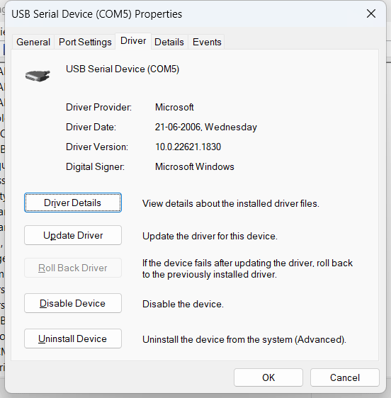
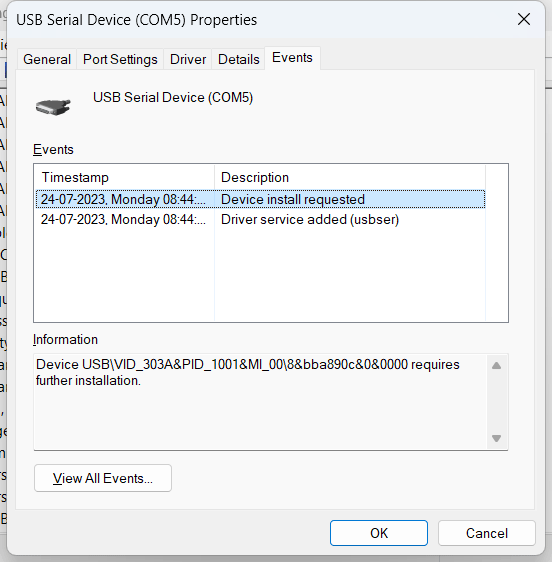
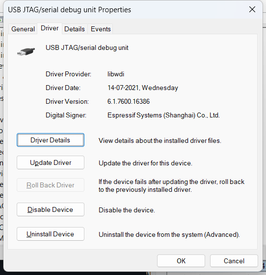
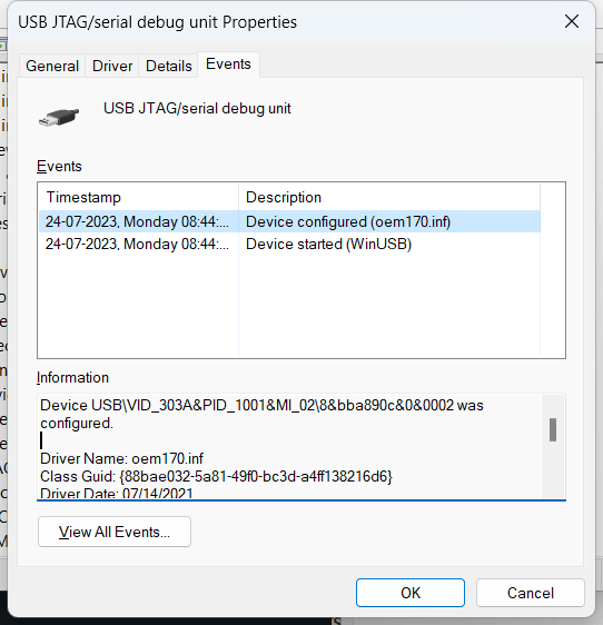
Now you can try uploading the sample code we have shown previously. If the debug probe is working correctly, the firmware will be uploaded using the JTAG protocol. If that is working, you can now try running a new debug session from Run → Start Debugging. You might get the following error when uploading the code. But it won’t affect the operation.
Error: libusb_open() failed with LIBUSB_ERROR_NOT_SUPPORTED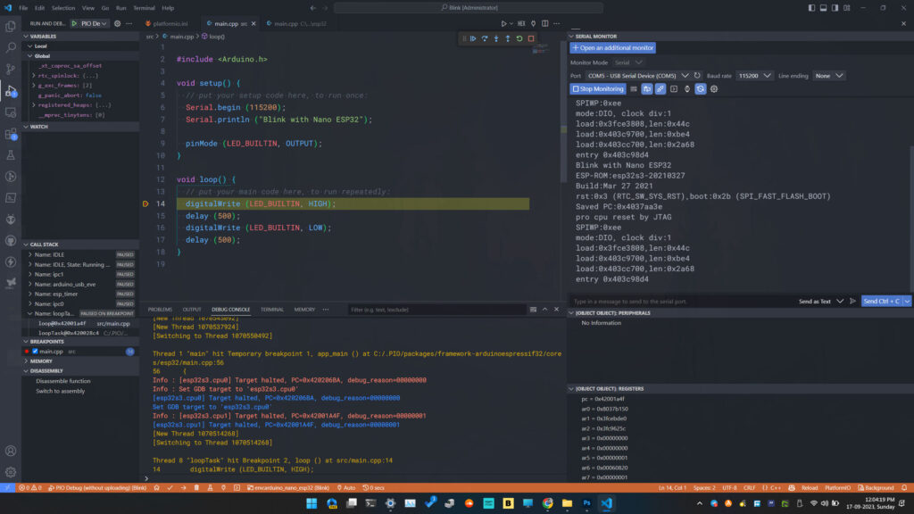
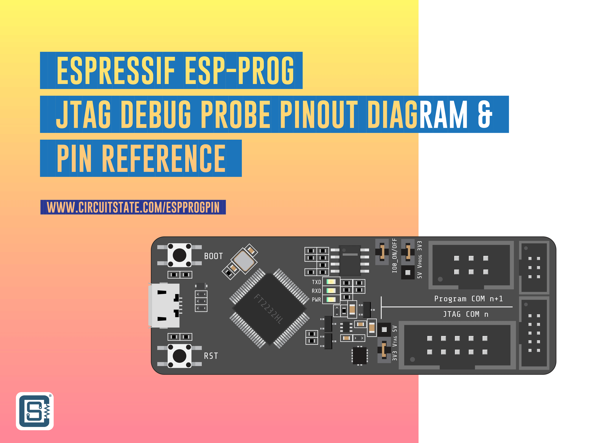
Using the native USB-JTAG of ESP32-S3 has some limitations as explained in the Espressif docs. The USB-JTAG debugging is also slow. If you want a faster debugging experience with many more breakpoints, you can consider getting the official ESP-Prog debug probe based on the FT2232HL USB-JTAG chip from FTDI.
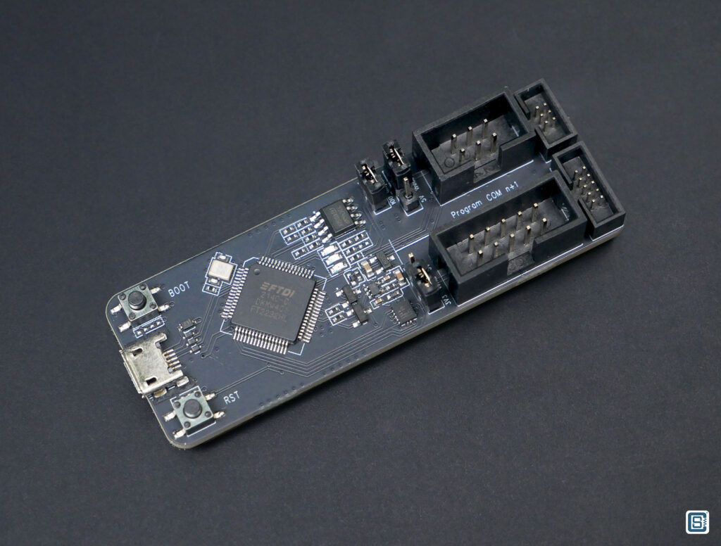
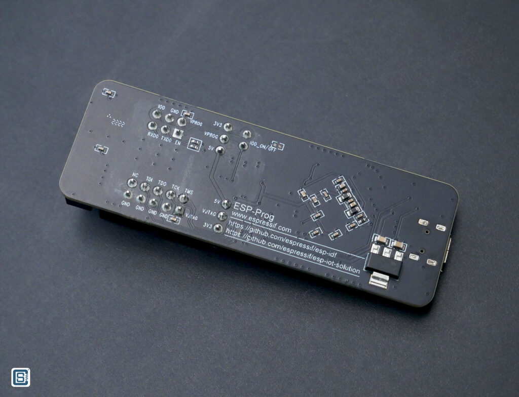
If you want to learn more about the ESP-Prog ESP debug probe, we have a dedicated tutorial where we show how you can debug any ESP32 board using ESP-Prog and the JTAG interface.
Espressif ESP-Prog ESP32 JTAG Debug Probe – Pinout Diagram
Example Programs
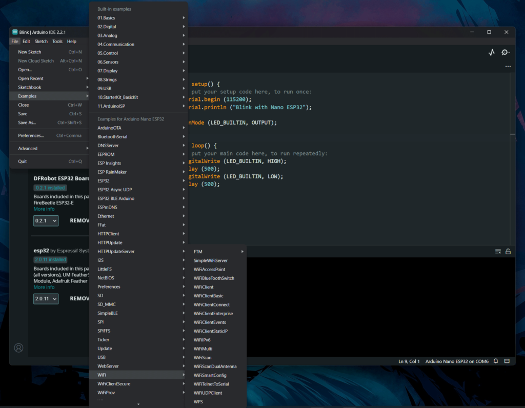
The ESP32 board package comes with many generic example sketches that you can use as the base for new projects. Arduino has published many examples exclusive to the Nano ESP32. You can find those examples from File → Examples → Examples for Arduino Nano ESP32. You need to select the official Arduino ESP32 package for these examples to show up.
Wi-Fi
There are many Wi-Fi-related examples available from Arduino. Here, we are going to show you how a simple web server can be implemented using the SimpleWiFiServer example. You can find this example sketch under the WiFi example category. The example makes the Nano ESP32 connect to an existing Wi-Fi network and start a simple HTTP web server from which you can turn an LED ON/OFF. The official example uses digital pin 5 for the LED connection. But we will use the built-in LED LED_BUILTIN. In place of yourssid and yourpassword, you need to enter the actual Wi-Fi network name and the password before uploading the code. Below is the modified example.
/*
 WiFi Web Server LED Blink

 A simple web server that lets you blink an LED via the web.
 This sketch will print the IP address of your WiFi Shield (once connected)
 to the Serial monitor. From there, you can open that address in a web browser
 to turn on and off the LED on pin 5.

 If the IP address of your shield is yourAddress:
 http://yourAddress/H turns the LED on
 http://yourAddress/L turns it off

 This example is written for a network using WPA2 encryption. For insecure
 WEP or WPA, change the Wifi.begin() call and use Wifi.setMinSecurity()
accordingly.

 Circuit:
 * WiFi shield attached
 * LED attached to pin 5

 created for arduino 25 Nov 2012
 by Tom Igoe

ported for sparkfun esp32
31.01.2017 by Jan Hendrik Berlin

 */

#include <WiFi.h>

const char* ssid = "yourssid";
const char* password = "yourpassword";

WiFiServer server (80);

void setup() {
  Serial.begin (115200);
  pinMode (LED_BUILTIN, OUTPUT);  // set the LED pin mode

  delay(10);

  // We start by connecting to a WiFi network
  Serial.println();
  Serial.println();
  Serial.print ("Connecting to ");
  Serial.println (ssid);

  WiFi.begin (ssid, password);

  while (WiFi.status() != WL_CONNECTED) {
    delay (500);
    Serial.print (".");
  }

  Serial.println ("");
  Serial.println ("WiFi connected.");
  Serial.println ("IP address: ");
  Serial.println (WiFi.localIP());

  server.begin();
}

void loop() {
  WiFiClient client = server.available();  // listen for incoming clients

  if (client) {                     // if you get a client,
    Serial.println ("New Client.");  // print a message out the serial port
    String currentLine = "";  // make a String to hold incoming data from the client

    while (client.connected()) {  // loop while the client's connected
      if (client.available()) {   // if there's bytes to read from the client,
        char c = client.read();   // read a byte, then
        Serial.write (c);          // print it out the serial monitor
        if (c == '\n') {          // if the byte is a newline character

          // if the current line is blank, you got two newline characters in a
          // row. that's the end of the client HTTP request, so send a response:
          if (currentLine.length() == 0) {
            // HTTP headers always start with a response code (e.g. HTTP/1.1 200
            // OK) and a content-type so the client knows what's coming, then a
            // blank line:
            client.println ("HTTP/1.1 200 OK");
            client.println ("Content-type:text/html");
            client.println();

            // the content of the HTTP response follows the header:
            client.print ("Click <a href=\"/H\">here</a> to turn the LED on.<br>");
            client.print ("Click <a href=\"/L\">here</a> to turn the LED off.<br>");

            // The HTTP response ends with another blank line:
            client.println();
            // break out of the while loop:
            break;
          } else {  // if you got a newline, then clear currentLine:
            currentLine = "";
          }
        } else if (c != '\r') {  // if you got anything else but a carriage return character,
          currentLine += c;      // add it to the end of the currentLine
        }

        // Check to see if the client request was "GET /H" or "GET /L":
        if (currentLine.endsWith ("GET /H")) {
          digitalWrite (LED_BUILTIN, HIGH);  // GET /H turns the LED on
        }
        if (currentLine.endsWith ("GET /L")) {
          digitalWrite (LED_BUILTIN, LOW);  // GET /L turns the LED off
        }
      }
    }
    // close the connection:
    client.stop();
    Serial.println ("Client Disconnected.");
  }
}
As soon as your board is connected to the Wi-Fi network, it will print the IP address assigned to it. The IP address is assigned by the Wi-Fi access point (AP, or the router) and can not be fixed. The AP will assign the next free IP when your board tries to connect. This makes the IP dynamic. You can open the serial monitor and reset the board to see the board’s IP address.
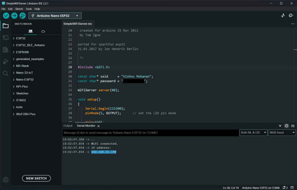
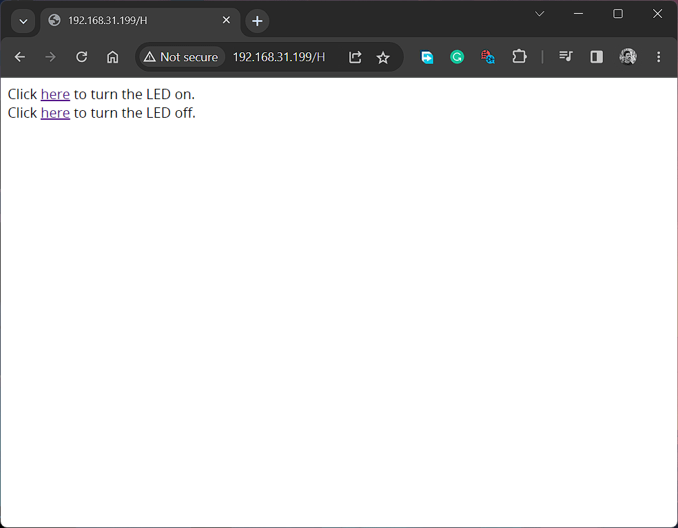
If you copy the IP address and paste it into a web browser, you will get a page like the one below. In our case, the IP address is 192.168.31.199. The board opens HTTP port 80 as soon as it is connected to the network. That is why we can open the page served by the Nano ESP32 board. You can click on the two links to either turn on or off the LED. When you click on the links, an extra parameter is sent with the address. The parameter is either H (High) or L (Low). When the web server receives this parameter, it turns the LED ON/OFF.
We can develop IoT applications for you
CIRCUITSTATE can develop and deploy IoT applications using industry-leading hardware, software, and cloud frameworks including AWS, Azure, Google IoT, Arduino IoT, ThingSpeak, Kaa IoT, Particle, etc. Contact us today to share your requirements.
Bluetooth LE
ESP32-S3 supports both Classic and Low Energy (LE) versions of Bluetooth. The Bluetooth version supported by ESP32-S3 is 5. To demonstrate the BLE feature of the Nano ESP32 board, we are going to create a simple Nordic UART Service example with which you can send and receive serial data using a serial monitor and the NRF Connect app from Nordic Semiconductor. Try uploading the following code to your Nano ESP32.
//==========================================================================================//
/*
  Based on Neil Kolban example for IDF:
  https://github.com/nkolban/esp32-snippets/blob/master/cpp_utils/tests/BLE%20Tests/SampleNotify.cpp

  Ported to Arduino ESP32 by Evandro Copercini. Modified by CIRCUITSTATE Electronics.

  This example created a BLE service with ID 6E400001-B5A3-F393-E0A9-E50E24DCCA9E
  (Nordic UART Service) and device name "UART Service". You can find the device by scanning
  the BLE. There are two associated characteristics:

  1. 6E400002-B5A3-F393-E0A9-E50E24DCCA9E - RX Characteristic

  Data you send through serial monitor will be received on the device end through this.

  2. 6E400003-B5A3-F393-E0A9-E50E24DCCA9E - TX Characteristic

  Data you send from the device uising Write operation will be sent back to the serial monitor
  though this.

  The design of creating the BLE server is:
  1. Create a BLE Server
  2. Create a BLE Service
  3. Create a BLE Characteristic on the Service
  4. Create a BLE Descriptor on the characteristic
  5. Start the service.
  6. Start advertising.
*/
//==========================================================================================//

#include <BLE2902.h>
#include <BLEDevice.h>
#include <BLEServer.h>
#include <BLEUtils.h>

//==========================================================================================//

BLEServer *pServer = NULL;
BLECharacteristic *pTxCharacteristic;
bool deviceConnected = false;
bool oldDeviceConnected = false;

//==========================================================================================//

// See the following for generating UUIDs:
// https://www.uuidgenerator.net/

#define SERVICE_UUID              "6E400001-B5A3-F393-E0A9-E50E24DCCA9E"  // UART service UUID
#define CHARACTERISTIC_UUID_RX    "6E400002-B5A3-F393-E0A9-E50E24DCCA9E"
#define CHARACTERISTIC_UUID_TX    "6E400003-B5A3-F393-E0A9-E50E24DCCA9E"

//==========================================================================================//

class MyServerCallbacks : public BLEServerCallbacks {
  void onConnect (BLEServer *pServer) { deviceConnected = true; };
  void onDisconnect (BLEServer *pServer) { deviceConnected = false; }
};

//==========================================================================================//

class MyCallbacks : public BLECharacteristicCallbacks {
  void onWrite (BLECharacteristic *pCharacteristic) {
    std::string rxValue = pCharacteristic->getValue();

    if (rxValue.length() > 0) {
      Serial.print ("Received Value: ");
      for (int i = 0; i < rxValue.length(); i++) Serial.print (rxValue [i]);

      Serial.println();
    }
  }
};

//==========================================================================================//

void setup() {
  Serial.begin (115200);

  // Create the BLE Device
  BLEDevice::init ("UART Service");

  // Create the BLE Server
  pServer = BLEDevice:: createServer();
  pServer->setCallbacks (new MyServerCallbacks());

  // Create the BLE Service
  BLEService *pService = pServer->createService (SERVICE_UUID);

  // Create a BLE Characteristic
  pTxCharacteristic = pService->createCharacteristic (CHARACTERISTIC_UUID_TX, BLECharacteristic::PROPERTY_NOTIFY);

  pTxCharacteristic->addDescriptor (new BLE2902());

  BLECharacteristic *pRxCharacteristic = pService->createCharacteristic (CHARACTERISTIC_UUID_RX, BLECharacteristic::PROPERTY_WRITE);

  pRxCharacteristic->setCallbacks (new MyCallbacks());

  // Start the service
  pService->start();

  // Start advertising
  pServer->getAdvertising()->start();
  Serial.println ("Waiting a client connection to notify..");
}

//==========================================================================================//

void loop() {
  if (deviceConnected) {
    if (Serial.available() > 0) {
      String serialString = Serial.readString();
      Serial.println ("Sending Value: " + serialString);
      pTxCharacteristic->setValue ((std::string) serialString.c_str());
      pTxCharacteristic->notify();
      delay (10);  // bluetooth stack will go into congestion, if too many packets are sent
    }
  }

  // disconnecting
  if (!deviceConnected && oldDeviceConnected) {
    delay (500);  // give the bluetooth stack the chance to get things ready
    pServer->startAdvertising();  // restart advertising
    Serial.println ("Start advertising");
    oldDeviceConnected = deviceConnected;
  }
  // connecting
  if (deviceConnected && !oldDeviceConnected) {
    // do stuff here on connecting
    oldDeviceConnected = deviceConnected;
  }
}

//==========================================================================================//
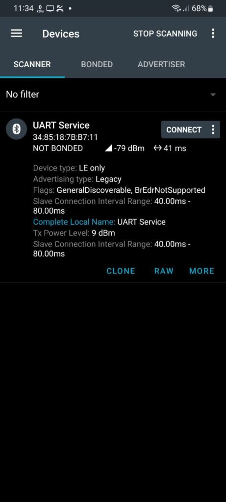
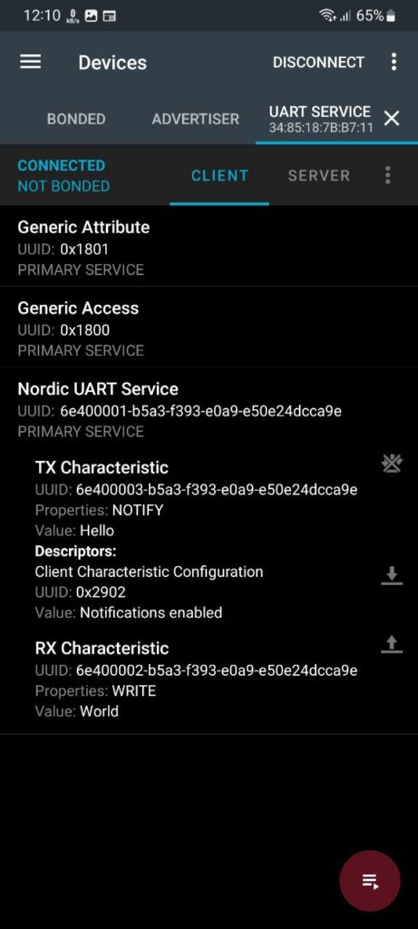
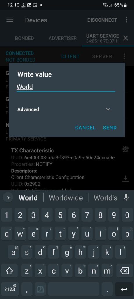
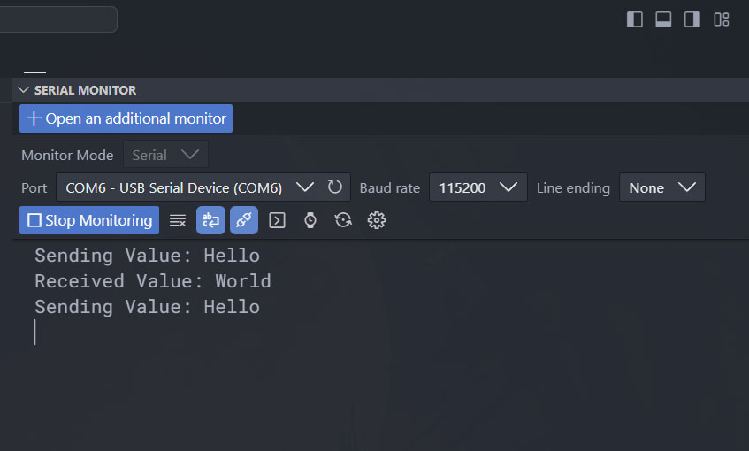
After uploading the code to your board, you can open the serial monitor with a baudrate 115200. To connect to the board, you first need to install the NRF Connect app on your smartphone and launch it. In the SCANNER window, you can scan for all Bluetooth devices and if the Nano ESP32 is up and running, you should see a device named “UART Service”. Connect to the device using the CONNECT button. After connecting, the app will open a new tab that lists all the services and characteristics served by the Bluetooth device. In our case, there is only a single BLE service Nordic UART Service, and the two characteristics associated with it; TX Characteristic and RX Characteristic. From the serial monitor, you can send any data and it will be received by the TX Characteristic. In order to see the data, simply enable the notification by tapping the triple download button on the app. Here, we are sending “Hello” from the serial monitor. The data will be shown as the Value in the app.
To send any data back to the serial monitor, you can use the RX Characteristic. Use the up-pointing button in the RX Characteristic to write a new value. Here, we are sending the value “World”. As soon as you hit SEND, the value will appear on the serial monitor.
That’s pretty much everything for this tutorial. If you know how to improve this tutorial, don’t hesitate to post it in the comments. In upcoming tutorials, we will learn more about the Arduino Nano ESP32. Happy tinkering 😉
Links
- Arduino Nano ESP32 – Arduino Store
- Arduino Nano ESP32 – Datasheet [PDF]
- Arduino Nano ESP32 – Schematic [PDF]
- Arduino Nano ESP32 – Full Pinout [PDF]
- ESP32-S3R8 – Digikey
- NORA-W106-10B – Product Page
- Getting Started with Arduino Nano 33 IoT Microcontroller Development Board – Pinout, Schematic & Example Programs
- Xtensa LX7 – Product Page
- ESP Product Selector
- Arduino ESP32 Boards – GitHub
- arduino-esp32 by Espressif – GitHub
- NRF Connect App
Short Link
- Short URL to this page – https://www.circuitstate.com/nanoesp32
