Getting Started with Arduino Nano 33 IoT Microcontroller Development Board – Pinout, Schematic & Example Programs
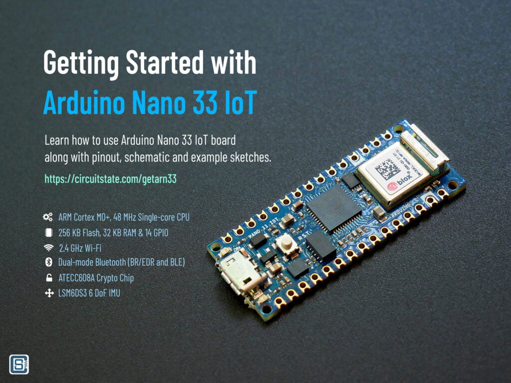
Arduino Nano 33 IoT is an official IoT-oriented microcontroller development board from Arduino. It is one of the few boards supported by all features provided by the Arduino IoT Cloud, out of the box. The board integrates a powerful 32-bit ARM Cortex-M0+ SAMD21 microprocessor from Microchip, u-blox NINA-W102 Wi-Fi and Bluetooth (BR/EDR, BLE) module, ATECC608 crypto chip from Microchip, and LSM6DS3 6-axis Inertial Measurement Unit (IMU) sensor from ST Microelectronics. The small form-factor board is breadboard-friendly and is the cheapest Wi-Fi-enabled board from Arduino. It costs around $18 in US stores and around Rs.1900 in Indian stores.
In this tutorial, we will learn about the hardware design, features, and programming of Arduino Nano 33 IoT. We will use both Arduino IDE and PlatformIO to create and run example programs demonstrating the Bluetooth, Wi-Fi, and sensing capabilities of the board.
We can develop embedded firmware for you
CIRCUITSTATE can develop embedded firmware for any microcontroller/microprocessor including 8051, PIC, AVR, ARM, STM32, ESP32, and RISC-V using industry-leading SDKs, frameworks, and tools. Contact us today to share your requirements.

Board Specifications
| Specification | Value |
|---|---|
| MICROCONTROLLER | SAMD21 Cortex®-M0+ 32bit low power ARM MCU (Datasheet) |
| RADIO MODULE | u-blox NINA-W102 (Datasheet) |
| SECURE ELEMENT | ATECC608A (Datasheet) |
| OPERATING VOLTAGE | 3.3 V |
| INPUT VOLTAGE (LIMIT) | 21 V |
| DC CURRENT PER I/O PIN | 7 mA |
| CLOCK SPEED | 48 MHz |
| CPU FLASH MEMORY | 256 KB |
| SRAM | 32 KB |
| EEPROM | none |
| DIGITAL INPUT / OUTPUT PINS | 14 |
| PWM PINS | 11 (2, 3, 5, 6, 9, 10, 11, 12, 16 / A2, 17 / A3, 19 / A5) |
| UART | 1 |
| SPI | 1 |
| I2C | 1 |
| ANALOG INPUT PINS | 8 (ADC 8/10/12 bit) |
| ANALOG OUTPUT PINS | 1 (DAC 10 bit) |
| EXTERNAL INTERRUPTS | All digital pins (all analog pins can also be used as interrput pins, but will have duplicated interrupt numbers) |
| LED_BUILTIN | 13 |
| USB | Native in the SAMD21 Processor |
| IMU | LSM6DS3 (Datasheet) |
| LENGTH | 45 mm |
| WIDTH | 18 mm |
| WEIGHT | 5 g (with headers) |
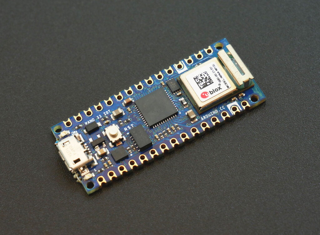
Atmel ATSAMD21G18
- Processor
- ARM® Cortex®-M0+ single core CPU running at up to 48 MHz
- Single-cycle hardware multiplier
- Micro Trace Buffer (MTB)
- Memories
- 256 KB in-system self-programmable Flash
- 32 KB SRAM Memory
- System
- Power-on Reset (POR) and Brown-out Detection (BOD)
- Internal and external clock options with 48 MHz Digital Frequency-Locked Loop (DFLL48M) and 48 MHz to 96 MHz Fractional Digital Phase-Locked Loop (FDPLL96M)
- Internal 32 KHz, 32 KHz ULP and 8 MHz oscillators
- External Interrupt Controller (EIC)
- 16 external interrupts
- One Non-maskable Interrupt (NMI)
- Two-pin Serial Wire Debug (SWD) programming, test and debugging interface
- Low Power
- Idle and Stand-by Sleep modes
- SleepWalking peripherals
- Peripherals
- 12-channel Direct Memory Access Controller (DMAC)
- 12-channel Event System
- Up to five 16-bit Timer/Counters (TC), configurable as either:
- One 16-bit TC with two compare/capture channels
- One 8-bit TC with two compare/capture channels
- One 32-bit TC with two compare/capture channels, by using two TCs
- Up to four 24-bit Timer/Counters for Control (TCC), with extended functions:
- Up to four compare channels with optional complementary output
- Generation of synchronized pulse width modulation (PWM) pattern across port pins
- Deterministic fault protection, fast decay and configurable dead-time between complementary output
- Dithering that increase resolution with up to 5 bit and reduce quantization error
- 32-bit Real Time Counter (RTC) with clock/calendar function
- Watchdog Timer (WDT)
- CRC-32 generator
- One full-speed (12 Mbps) Universal Serial Bus (USB) 2.0 interface
- Embedded host and device function
- Eight endpoints
- Up to six Serial Communication Interfaces (SERCOM), each configurable to operate as either:
- USART with full-duplex and single-wire half-duplex configuration
- I2C up to 3.4 MHz
- SPI
- LIN slave
- One two-channel Inter-IC Sound (I2S) interface
- One 12-bit, 350ksps Analog-to-Digital Converter (ADC) with up to 20 channels
- Differential and single-ended input
- 1/2x to 16x programmable gain stage
- Automatic offset and gain error compensation
- Oversampling and decimation in hardware to support 13-, 14-, 15- or 16-bit resolution
- 10-bit, 350 ksps Digital-to-Analog Converter (DAC)
- Up to four Analog Comparators (AC) with Window Compare function
- Peripheral Touch Controller (PTC)
- 256-Channel capacitive touch and proximity sensing
- I/O
- 38 programmable I/O pins
- Qualification
- AEC-Q100 Grade 1 (-40°C to 125°C)
- Drop-in compatible with SAM D20
- Packages
- 48-pin TQFP
- 48-pin QFN
- 48-pin WLCSP
- Operating Voltage
- 1.62V – 3.63V
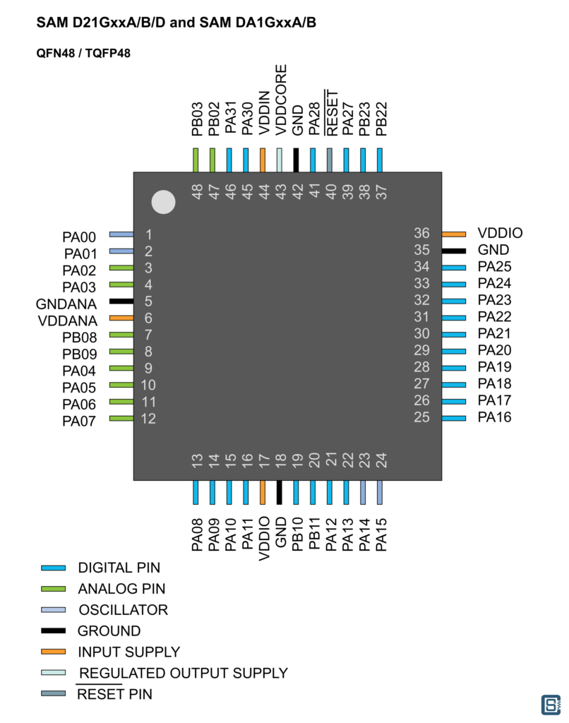
The specific model used in Arduino Nano 33 IoT is the ATSAMD21G18A-U with 48-pin QFN package. The pinout is as follows.
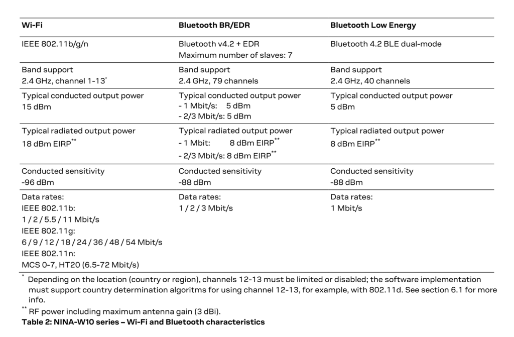
u-blox NINA-W102
- CPU
- Dual-core ESP32 32-bit Xtensa LX6 CPUs
- Max 240 MHz clock speed
- Memory
- 448 Kbyte ROM for booting and core functions
- 520 Kbyte SRAM for data and instruction
- 16 Mbit (2MB) FLASH for code storage including hardware encryption to protect programs and data
- 1 kbit EFUSE (non-erasable memory) for MAC addresses, module configuration, FlashEncryption, and Chip-ID
- Wi-Fi
- Wi-Fi 802.11b/g/n
- Access point
- Factory programmed MAC address(es)
- FOTA according to CTCC/CMCC
- Point-to-point protocol (PPP)
- Wi-Fi enterprise security
- WPA3
- Wi-Fi output power EIRP: 18 dBm
- Throughput: 25 Mbits/s
- Wi-Fi micro access point: max 10 stations
- Maximum Wi-Fi range: 400 m
- Wi-Fi frequency: 2.4 GHz
- Bluetooth
- Dual-mode Bluetooth with both BR/EDR and BLE
- Bluetooth qualification: 4.2
- Simultaneous GATT server and client
- Bluetooth output power EIRP: 8 dBm
- Maximum Bluetooth range: 200 m
- Bluetooth SPP
- Bluetooth DUN
- Bluetooth PAN
- Bluetooth GATT
- I/O
- UART: 3
- SPI: 3
- TWI (I2C compatible): 3
- I2S: 1
- SDIO: 1
- Ethernet RMII: 1
- JTAG: 1
- GPIO: 24
- ADC: 4
- Working voltage: 3-3.6V (3.3V recommended)
- Temperature: -40 to 85°C
- Dimensions: 10 x 14 x 3.8 mm


ATECC608A
- Cryptographic Co-Processor with Secure Hardware-Based Key Storage:
- Protected storage for up to 16 keys, certificates or data
- Hardware Support for Asymmetric Sign, Verify, Key Agreement:
- ECDSA: FIPS186-3 Elliptic Curve Digital Signature
- ECDH: FIPS SP800-56A Elliptic Curve Diffie-Hellman
- NIST Standard P256 Elliptic Curve Support
- Hardware Support for Symmetric Algorithms:
- SHA-256 & HMAC Hash including off-chip context save/restore
- AES-128: Encrypt/Decrypt, Galois Field Multiply for GCM
- Networking Key Management Support:
- Turnkey PRF/HKDF calculation for TLS 1.2 & 1.3
- Ephemeral key generation and key agreement in SRAM
- Small message encryption with keys entirely protected
- Secure Boot Support:
- Full ECDSA code signature validation, optional stored digest/signature
- Optional communication key disablement prior to secure boot
- Encryption/Authentication for messages to prevent on-board attacks
- Internal High-Quality NIST SP 800-90A/B/C Random Number Generator (RNG)
- Two High-Endurance Monotonic Counters
- Unique 72-Bit Serial Number
- Two Interface Options Available:
- High-speed Single Pin Interface with One GPIO Pin
- 1 MHz Standard I2C Interface
- 1.8V to 5.5V IO Levels, 2.0V to 5.5V Supply Voltage
- <150 nA Sleep Current
- 8-pad UDFN and 8-lead SOIC
LSM6DS3
- Power consumption: 0.9 mA in combo normal mode and 1.25 mA in combo high-performance mode up to 1.6 kHz.
- “Always-on” experience with low power consumption for both accelerometer and gyroscope
- Smart FIFO up to 8 kbyte based on features set
- Compliant with Android K and L
- Hard, soft ironing for external magnetic sensor corrections
- ±2/±4/±8/±16 g full scale
- ±125/±250/±500/±1000/±2000 dps full scale
- Analog supply voltage: 1.71 V to 3.6 V
- Independent IOs supply (1.62 V)
- Compact footprint, 2.5 mm x 3 mm x 0.83 mm
- SPI/I2C serial interface with main processor data synchronization feature
- Embedded temperature sensor
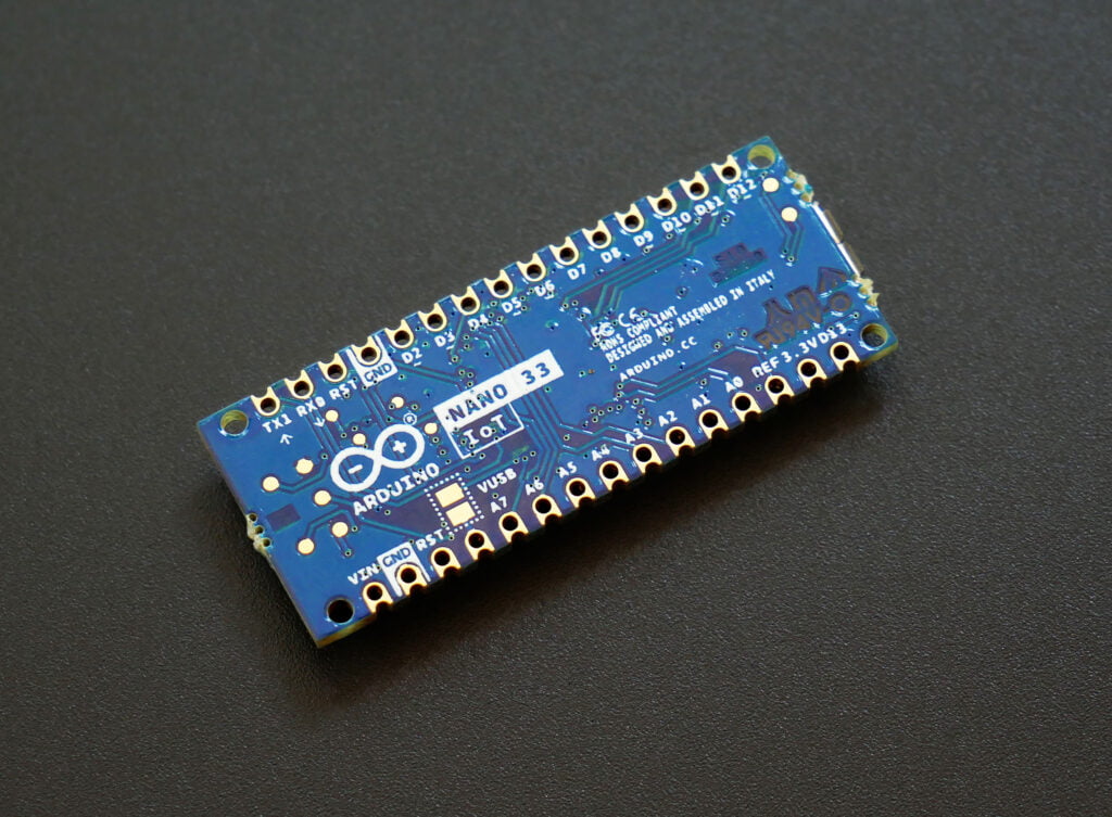
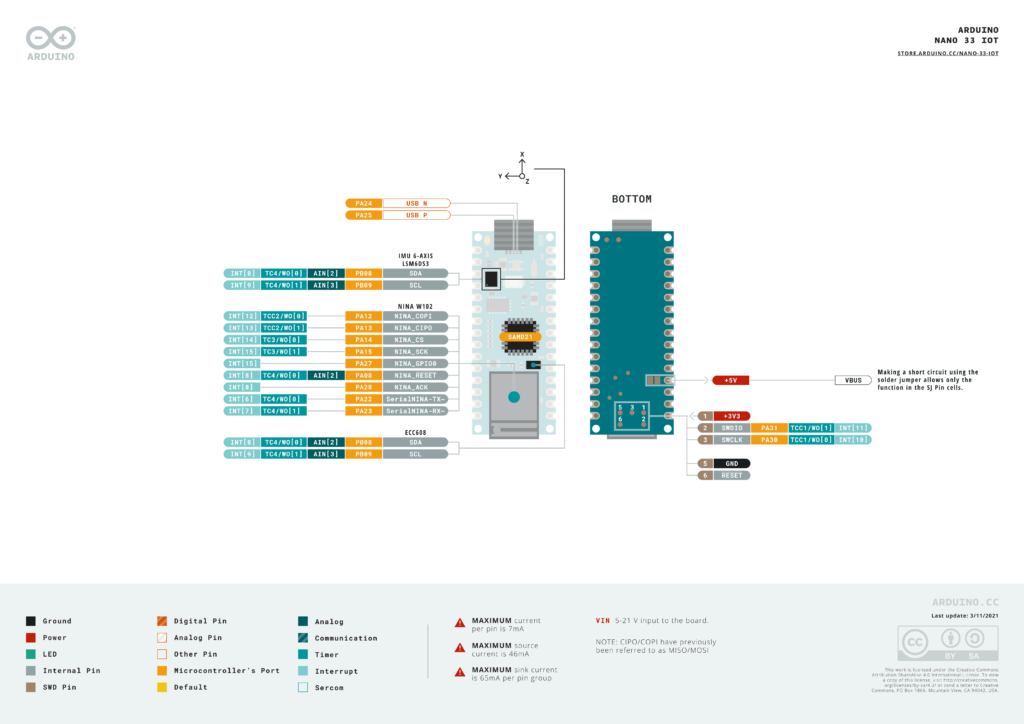
Pinout

Schematic


Mechanical Dimensions

Programming
We will first explain how you can set up your Nano 33 IoT board on different IDEs. Once set up, you can try the example sketches available in the IDE.
Arduino IDE v1.8
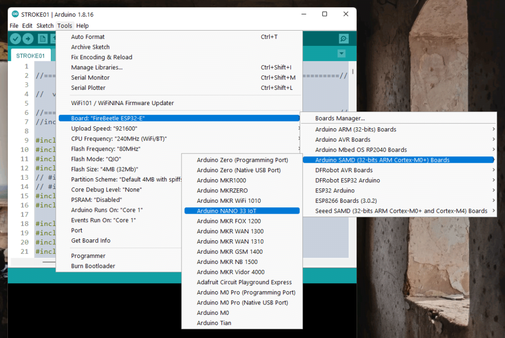
Before you can program your Arduino Nano 33 IoT, you need to install the required packages and board definitions. Open your Arduino IDE and browse to Tools → Board → Board Manager. Then search for “nano 33 ioT” and install the Arduino SAMD Boards (32-bits ARM Cortex-M0+) package. This SAMD package (SAMD21) is different from the package used for boards like Arduino Due.
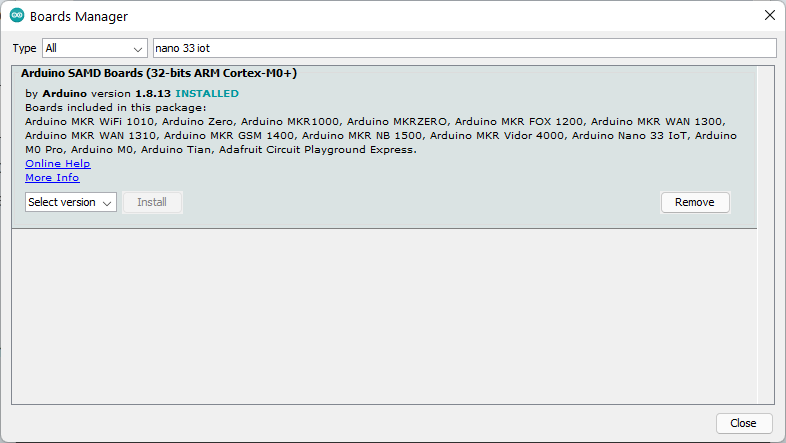
Once you have installed the package, a new list of boards will appear under Tools → Board → Arduino SAMD (32-bits ARM Cortex-M0+) Boards. Choose Arduino Nano 33 IoT from the list.
You can try the example Blink sketch from File → Examples → 01.Basics → Blink. Choose the port from Tools → Port and then click Upload.
Arduino IDE v2.0
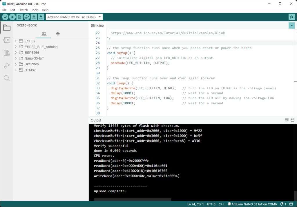
Similar to the IDE v1.8, you need to install the board packages before you can compile and upload your sketches. Use Boards Manager from the left menu pane and search for “nano 33 iot” and install the latest version of Arduino SAMD Boards (32-bits ARM Cortex-M0+) package. Then open the Blink sketch from File → Examples → 01.Basics → Blink. Choose the port from the top and click Upload.
VS Code + Arduino Extension
If you have either Arduino IDE or Arduino CLI installed on your system, then you can use VS Code + Arduino extension to write, compile, and upload Arduino sketches to your boards. We have a complete tutorial on using VS Code and its Arduino extension to develop Arduino projects. We used the Nano 33 IoT board for the demo.
How to Use VS Code for Creating and Uploading Arduino Sketches
You can try all Arduino examples right from VS Code.

VS Code + PlatformIO Extension
PlatformIO (PIO) is a unified, multi-framework integrated development platform for embedded devices. It runs on top of other IDEs like VS Code and Atom. It is also available as a CLI (Command Line Interface) client. If you have VS Code and PlatformIO extension installed, it is easy to get started with Arduino Nano 33 IoT on PIO.

If everything is installed correctly, open the PIO home page and click on the New Project button. Search for “nano 33” and choose the Nano 33 IoT (Arduino) from the list. Choose Arduino as the framework. If you are only starting to use PIO, you will need to install Arduino framework and Atmel SAM embedded platform, before you can create a project.


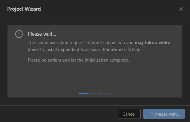
We will name the project Nano-33-IoT-Blink and save it to the default location. When you click Finish, PIO will start to download all the remaining dependencies for creating the project. You need an internet connection here and the process may take a while.
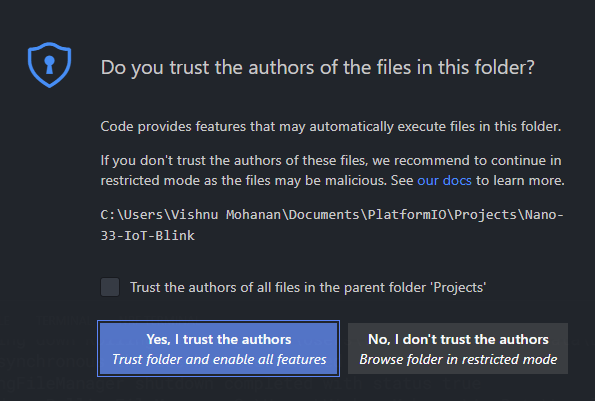
If VS Code prompts, Do you trust the authors of files in the folder?, then choose Yes, I trust the authors. This is just a security check.
PIO will generate the project files and open the platformio.ini file for adding configurations.
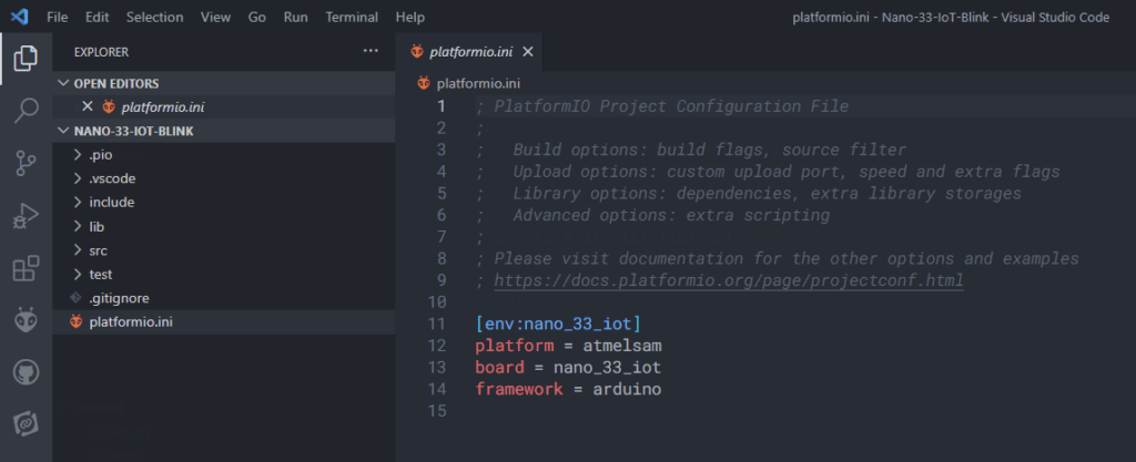
Next, find the Build and Upload buttons on the tasks menu for building and uploading your project. If you have multiple devices connected to the computer, you will need to specify the serial port in platformio.ini using the upload_port definition.

Following is the compilation log.
> Executing task: C:\.PIO\penv\Scripts\platformio.exe run --environment nano_33_iot <

Processing nano_33_iot (platform: atmelsam; board: nano_33_iot; framework: arduino)
--------------------------------------------------------------------------------------------------------------------------------------------------------------------
Verbose mode can be enabled via `-v, --verbose` option
CONFIGURATION: https://docs.platformio.org/page/boards/atmelsam/nano_33_iot.html
PLATFORM: Atmel SAM (7.1.0) > NANO 33 IoT
HARDWARE: SAMD21G18A 48MHz, 32KB RAM, 256KB Flash
DEBUG: Current (atmel-ice) External (atmel-ice, blackmagic, jlink)
PACKAGES:
 - framework-arduino-samd 1.8.11
 - framework-cmsis 1.40500.0 (4.5.0)
 - framework-cmsis-atmel 1.2.2
 - toolchain-gccarmnoneeabi 1.70201.0 (7.2.1)
LDF: Library Dependency Finder -> https://bit.ly/configure-pio-ldf
LDF Modes: Finder ~ chain, Compatibility ~ soft
Found 12 compatible libraries
Scanning dependencies...
No dependencies
Building in release mode
Compiling .pio\build\nano_33_iot\src\main.cpp.o
Compiling .pio\build\nano_33_iot\FrameworkArduinoVariant\variant.cpp.o
Compiling .pio\build\nano_33_iot\FrameworkArduino\Reset.cpp.o
Compiling .pio\build\nano_33_iot\FrameworkArduino\SERCOM.cpp.o
Compiling .pio\build\nano_33_iot\FrameworkArduino\Tone.cpp.o
Compiling .pio\build\nano_33_iot\FrameworkArduino\USB\CDC.cpp.o
Compiling .pio\build\nano_33_iot\FrameworkArduino\USB\USBCore.cpp.o
Compiling .pio\build\nano_33_iot\FrameworkArduino\USB\samd21_host.c.o
Compiling .pio\build\nano_33_iot\FrameworkArduino\Uart.cpp.o
Compiling .pio\build\nano_33_iot\FrameworkArduino\WInterrupts.c.o
Compiling .pio\build\nano_33_iot\FrameworkArduino\WMath.cpp.o
Compiling .pio\build\nano_33_iot\FrameworkArduino\abi.cpp.o
Compiling .pio\build\nano_33_iot\FrameworkArduino\api\Common.cpp.o
Compiling .pio\build\nano_33_iot\FrameworkArduino\api\IPAddress.cpp.o
Compiling .pio\build\nano_33_iot\FrameworkArduino\api\PluggableUSB.cpp.o
Compiling .pio\build\nano_33_iot\FrameworkArduino\api\Print.cpp.o
In file included from C:\.PIO\packages\framework-arduino-samd\cores\arduino/Uart.h:23:0,
                 from C:\.PIO\packages\framework-arduino-samd\variants\nano_33_iot/variant.h:179,
                 from C:\.PIO\packages\framework-arduino-samd\cores\arduino\Arduino.h:48,
                 from C:\.PIO\packages\framework-arduino-samd\cores\arduino\Uart.cpp:19:
C:\.PIO\packages\framework-arduino-samd\cores\arduino/SafeRingBuffer.h: In member function 'int arduino::SafeRingBufferN<N>::read_char() [with int N = 64]':
C:\.PIO\packages\framework-arduino-samd\cores\arduino/SafeRingBuffer.h:44:1: warning: control reaches end of non-void function [-Wreturn-type]
 }
 ^
Compiling .pio\build\nano_33_iot\FrameworkArduino\api\Stream.cpp.o
Archiving .pio\build\nano_33_iot\libFrameworkArduinoVariant.a
Compiling .pio\build\nano_33_iot\FrameworkArduino\api\String.cpp.o
Compiling .pio\build\nano_33_iot\FrameworkArduino\compact\dtostrf.c.o
Compiling .pio\build\nano_33_iot\FrameworkArduino\cortex_handlers.c.o
Compiling .pio\build\nano_33_iot\FrameworkArduino\delay.c.o
Compiling .pio\build\nano_33_iot\FrameworkArduino\hooks.c.o
Compiling .pio\build\nano_33_iot\FrameworkArduino\itoa.c.o
Compiling .pio\build\nano_33_iot\FrameworkArduino\main.cpp.o
Compiling .pio\build\nano_33_iot\FrameworkArduino\new.cpp.o
Compiling .pio\build\nano_33_iot\FrameworkArduino\pulse.c.o
Compiling .pio\build\nano_33_iot\FrameworkArduino\pulse_asm.S.o
Compiling .pio\build\nano_33_iot\FrameworkArduino\startup.c.o
Compiling .pio\build\nano_33_iot\FrameworkArduino\wiring.c.o
Compiling .pio\build\nano_33_iot\FrameworkArduino\wiring_analog.c.o
Compiling .pio\build\nano_33_iot\FrameworkArduino\wiring_digital.c.o
Compiling .pio\build\nano_33_iot\FrameworkArduino\wiring_private.c.o
Compiling .pio\build\nano_33_iot\FrameworkArduino\wiring_shift.c.o
Indexing .pio\build\nano_33_iot\libFrameworkArduinoVariant.a
Archiving .pio\build\nano_33_iot\libFrameworkArduino.a
Indexing .pio\build\nano_33_iot\libFrameworkArduino.a
Linking .pio\build\nano_33_iot\firmware.elf
Checking size .pio\build\nano_33_iot\firmware.elf
Advanced Memory Usage is available via "PlatformIO Home > Project Inspect"
RAM:   [=         ]   7.3% (used 2384 bytes from 32768 bytes)
Flash: [          ]   4.3% (used 11216 bytes from 262144 bytes)
Building .pio\build\nano_33_iot\firmware.bin
=================================================================== [SUCCESS] Took 3.91 seconds ===================================================================

Terminal will be reused by tasks, press any key to close it.
Following is the upload log.
> Executing task: C:\.PIO\penv\Scripts\platformio.exe run --target upload --environment nano_33_iot <

Processing nano_33_iot (platform: atmelsam; board: nano_33_iot; framework: arduino)
-----------------------------------------------------------------------------------------------------------------------------------------------------
Tool Manager: Installing platformio/tool-bossac @ ~1.10700.0
Downloading  [####################################]  100%
Unpacking  [####################################]  100%
Tool Manager: tool-bossac @ 1.10700.190624 has been installed!
Verbose mode can be enabled via `-v, --verbose` option
CONFIGURATION: https://docs.platformio.org/page/boards/atmelsam/nano_33_iot.html
PLATFORM: Atmel SAM (7.1.0) > NANO 33 IoT
HARDWARE: SAMD21G18A 48MHz, 32KB RAM, 256KB Flash
DEBUG: Current (atmel-ice) External (atmel-ice, blackmagic, jlink)
PACKAGES:
 - framework-arduino-samd 1.8.11
 - framework-cmsis 1.40500.0 (4.5.0)
 - framework-cmsis-atmel 1.2.2
 - tool-bossac 1.10700.190624 (1.7.0)
 - toolchain-gccarmnoneeabi 1.70201.0 (7.2.1)
LDF: Library Dependency Finder -> https://bit.ly/configure-pio-ldf
LDF Modes: Finder ~ chain, Compatibility ~ soft
Found 12 compatible libraries
Scanning dependencies...
No dependencies
Building in release mode
Checking size .pio\build\nano_33_iot\firmware.elf
Advanced Memory Usage is available via "PlatformIO Home > Project Inspect"
RAM:   [=         ]   7.3% (used 2384 bytes from 32768 bytes)
Flash: [          ]   4.3% (used 11216 bytes from 262144 bytes)
Configuring upload protocol...
AVAILABLE: atmel-ice, blackmagic, jlink, sam-ba
CURRENT: upload_protocol = sam-ba
Looking for upload port...
Auto-detected: COM6
Forcing reset using 1200bps open/close on port COM6
Waiting for the new upload port...
Uploading .pio\build\nano_33_iot\firmware.bin
Atmel SMART device 0x10010005 found
Erase flash
done in 0.837 seconds

Write 11216 bytes to flash (176 pages)

[==========                    ] 36% (64/176 pages)
[=====================         ] 72% (128/176 pages)
[==============================] 100% (176/176 pages)
done in 0.085 seconds

Verify 11216 bytes of flash with checksum.
Verify successful
done in 0.010 seconds
CPU reset.
=========================================================== [SUCCESS] Took 10.43 seconds ===========================================================

Terminal will be reused by tasks, press any key to close it.
Interestingly, the binary created by PIO is larger than what is created by the Arduino IDE, but the RAM usage is less. Flash usage is 4.3% (11216 bytes) and RAM usage is 7.3% (2384 bytes). This is because the optimization flags (-O0, –O2, -O3 etc) used by Arduino and PlatformIO are different.
You can also debug your programs using a PIO-compatible debugger such as JLINK, Black Magic Probe, etc. The Arduino Nano 33 IoT has pads on the bottom side of the board to access the SWD debug port. You need to solder wires there or use a jig to interface the debugger. We will cover this topic in a later post.
Example Sketches
Example sketches provided by Arduino and other libraries can be compiled on all IDEs and platforms explained above. We will use Arduino IDE 1.8 here to run the examples.
Blink
Open the Blink sketch from File → Examples → 01.Basics → Blink. LED_BUILTIN is the digital pin the onboard LED is connected to. In Arduino Nano 33 IoT, this is the D13 digital pin. We will blink the LED every 1 second (500ms).
// the setup function runs once when you press reset or power the board
void setup() {
  // initialize digital pin LED_BUILTIN as an output.
  pinMode (LED_BUILTIN, OUTPUT);
}

// the loop function runs over and over again forever
void loop() {
  digitalWrite (LED_BUILTIN, HIGH);   // turn the LED on (HIGH is the voltage level)
  delay (500);                       // wait for a second
  digitalWrite (LED_BUILTIN, LOW);    // turn the LED off by making the voltage LOW
  delay (500);                       // wait for a second
}
Choose the port to which the board is connected and upload the sketch. The following information will be printed to the terminal if you have the verbose output option enabled. Following is the upload log.
Sketch uses 11448 bytes (4%) of program storage space. Maximum is 262144 bytes.
Global variables use 3560 bytes (10%) of dynamic memory, leaving 29208 bytes for local variables. Maximum is 32768 bytes.
Forcing reset using 1200bps open/close on port COM6
PORTS {COM6, } / {} => {}
PORTS {} / {COM7, } => {COM7, }
Found upload port: COM7
C:\Users\Vishnu Mohanan\AppData\Local\Arduino15\packages\arduino\tools\bossac\1.7.0-arduino3/bossac.exe -i -d --port=COM7 -U true -i -e -w -v C:\Users\VISHNU~1\AppData\Local\Temp\arduino_build_738178/Blink.ino.bin -R
Set binary mode
readWord(addr=0)=0x20007ffc
readWord(addr=0xe000ed00)=0x410cc601
readWord(addr=0x41002018)=0x10010305
version()=v2.0 [Arduino:XYZ] Apr 19 2019 14:38:48
chipId=0x10010005
Connected at 921600 baud
readWord(addr=0)=0x20007ffc
readWord(addr=0xe000ed00)=0x410cc601
readWord(addr=0x41002018)=0x10010305
Atmel SMART device 0x10010005 found
write(addr=0x20004000,size=0x34)
writeWord(addr=0x20004030,value=0x10)
writeWord(addr=0x20004020,value=0x20008000)
Device       : ATSAMD21G18A
readWord(addr=0)=0x20007ffc
readWord(addr=0xe000ed00)=0x410cc601
readWord(addr=0x41002018)=0x10010305
Chip ID      : 10010005
version()=v2.0 [Arduino:XYZ] Apr 19 2019 14:38:48
Version      : v2.0 [Arduino:XYZ] Apr 19 2019 14:38:48
Address      : 8192
Pages        : 3968
Page Size    : 64 bytes
Total Size   : 248KB
Planes       : 1
Lock Regions : 16
Locked       : readWord(addr=0x41004020)=0xffff
readWord(addr=0x41004020)=0xffff
readWord(addr=0x41004020)=0xffff
readWord(addr=0x41004020)=0xffff
readWord(addr=0x41004020)=0xffff
readWord(addr=0x41004020)=0xffff
readWord(addr=0x41004020)=0xffff
readWord(addr=0x41004020)=0xffff
readWord(addr=0x41004020)=0xffff
readWord(addr=0x41004020)=0xffff
readWord(addr=0x41004020)=0xffff
readWord(addr=0x41004020)=0xffff
readWord(addr=0x41004020)=0xffff
readWord(addr=0x41004020)=0xffff
readWord(addr=0x41004020)=0xffff
readWord(addr=0x41004020)=0xffff
none
readWord(addr=0x41004018)=0
Security     : false
Boot Flash   : true
readWord(addr=0x40000834)=0x7000a
BOD          : true
readWord(addr=0x40000834)=0x7000a
BOR          : true
Arduino      : FAST_CHIP_ERASE
Arduino      : FAST_MULTI_PAGE_WRITE
Arduino      : CAN_CHECKSUM_MEMORY_BUFFER
Erase flash
chipErase(addr=0x2000)
done in 0.827 seconds

Write 11448 bytes to flash (179 pages)
write(addr=0x20005000,size=0x1000)
writeBuffer(scr_addr=0x20005000, dst_addr=0x2000, size=0x1000)
[==========                    ] 35% (64/179 pages)write(addr=0x20005000,size=0x1000)
writeBuffer(scr_addr=0x20005000, dst_addr=0x3000, size=0x1000)
[=====================         ] 71% (128/179 pages)write(addr=0x20005000,size=0xcc0)
writeBuffer(scr_addr=0x20005000, dst_addr=0x4000, size=0xcc0)
[==============================] 100% (179/179 pages)
done in 0.099 seconds

Verify 11448 bytes of flash with checksum.
checksumBuffer(start_addr=0x2000, size=0x1000) = 1e24
checksumBuffer(start_addr=0x3000, size=0x1000) = bc5f
checksumBuffer(start_addr=0x4000, size=0xcb8) = a336
Verify successful
done in 0.009 seconds
CPU reset.
readWord(addr=0)=0x20007ffc
readWord(addr=0xe000ed00)=0x410cc601
readWord(addr=0x41002018)=0x10010305
writeWord(addr=0xe000ed0c,value=0x5fa0004)
As you can see, the Blink sketch only uses 11448 bytes (4%) of program storage which has a maximum of 262144 bytes. Global variables use 3560 bytes (10%) of dynamic memory and leave 29208 bytes for the rest of the local variables.
LSM6DS3 Accelerometer
LSM6DS3 is an Inertial Measurement Unit (IMU) with a 3-axis accelerometer and 3-axis gyroscope. You need to install the Arduino_LSM6DS3 library to use the sensor on Nano 33 IoT. Install library from Sketch → Include Library → Manage Libraries by searching for “LSM6DS3”.
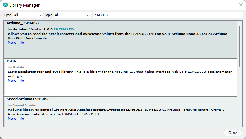
The library has two examples, one for the accelerometer and one for the gyroscope. Let’s try the SimpleAccelerometer example.
/*
  Arduino LSM6DS3 - Simple Accelerometer

  This example reads the acceleration values from the LSM6DS3
  sensor and continuously prints them to the Serial Monitor
  or Serial Plotter.

  The circuit:
  - Arduino Uno WiFi Rev 2 or Arduino Nano 33 IoT

  created 10 Jul 2019
  by Riccardo Rizzo

  This example code is in the public domain.
*/

#include <Arduino_LSM6DS3.h>

void setup() {
  Serial.begin (9600);
  while (!Serial);

  if (!IMU.begin()) {
    Serial.println ("Failed to initialize IMU!");

    while (1);
  }

  Serial.print ("Accelerometer sample rate = ");
  Serial.print (IMU.accelerationSampleRate());
  Serial.println (" Hz");
  Serial.println();
  Serial.println ("Acceleration in G's");
  Serial.println ("X\tY\tZ");
}

void loop() {
  float x, y, z;

  if (IMU.accelerationAvailable()) {
    IMU.readAcceleration (x, y, z);

    Serial.print (x);
    Serial.print ('\t');
    Serial.print (y);
    Serial.print ('\t');
    Serial.println (z);
  }
}
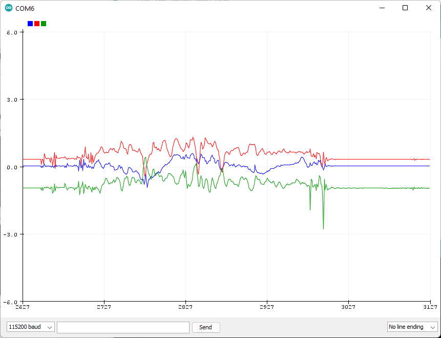
The data from the accelerometer can be viewed on a serial monitor or serial plotter.

Bluetooth BLE
Nano 33 IoT has a dual-mode Bluetooth module. The NINA-W102 module supports both Classic Bluetooth (BR/EDR) and Bluetooth Low Energy (BLE). To use the BLE feature of the board, you can install the ArduinoBLE from the library manager. The BLE examples can be opened from File → Examples → ArduinoBLE.

Let’s try the BatteryMonitor example. This program creates a demo battery service. You can use applications such as LightBlue or nRF Connect to connect to the device and observe the data sent by the device.
You need to open the serial monitor to start the BLE service. Fake battery values are generated by reading the A0 analog pin and published to the battery service.


Wi-Fi & Arduino IoT Cloud
We have a complete Wi-Fi and Arduino IoT Cloud example in a different post. We have used Arduino Nano 33 IoT for the demo.
How to Create Your First IoT Project – Arduino Cloud Tutorial with Arduino Nano 33 IoT
Hope we have covered enough about Nano 33 IoT board to get you started. Let us know what projects you develop with your Nano 33 IoT board. We will publish more specific applications and projects with Nano 33 IoT in the future.
Links
- Arduino Nano 33 IoT – Official Store
- Arduino Nano 33 IoT – Official Documentation
- Arduino Nano 33 IoT – Datasheet
- ARM Cortex-M0+ SAMD21 – Product Page
- u-blox NINA-W102 – Product Page
- LSM6DS3 – Product Page
- Download VS Code
- Arduino Extension for VS Code
- PlatformIO Extension for VS Code
Short Link
- Short URL to this page – https://circuitstate.com/getarn33


