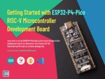
Getting Started with Waveshare ESP32-P4-Pico Microcontroller Development Board
Learn how to use the ESP32-P4-Pico high-performance microcontroller development board from Waveshare. Use Arduino, ESP IDF, PlatformIO and VS Code for software development.

There is no denial that Espressif is the company that brought wireless connectivity to the masses, through their ESP series of wireless SoCs. Their products have wireless connectivity as a default feature. Any electronic engineer anywhere in the world thinking about adding wireless connectivity in their projects will have the ESP in the list. But not all projects require wireless connectivity, or need more than just connectivity. Espressif had a lack of products that catered to such applications until now. The ESP32-P4 is a latest addition to the ESP product family that incorporates high-performance dual-core RISC-V microcontroller along with a rich set of peripherals. Notably, the P4 is missing any wireless capabilities. Instead, the whole chip is dedicated to not just two, but three CPU cores, and a plethora of modern interface features such as USB, CAN, Ethernet, SDIO and MIPI-CSI/DSI. If your next project requires a powerful and low-cost MCU with these capabilities, the ESP32-P4 is a good candidate. In this tutorial, we will take a closer look at the ESP32-P4 microcontroller and give you all information to get started. If you want to check out our last ESP32 tutorial, follow the link below.

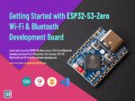
Getting Started with ESP32-S3 Wi-Fi & Bluetooth SoC using ESP32-S3-DEV-KIT-NxR8
Learn how to use Espressif ESP32-S3 SoC for Wi-Fi and Bluetooth development using the Waveshare ESP32-S3-DEV-KIT-NxR8 development board. Use Arduino, ESP-IDF, PlatformIO and VS Code for software development.
Waveshare ESP32-P4-Pico


ESP32-P4-Pico is an ESP32-P4 microcontroller development board from Waveshare. The ESP32-P4 is the most high-performance microcontroller from Espressif to date. The board has the same form-factor as the Raspberry Pi Pico and integrates the ESP32-P4NRW32 SoC variant with a 32 MB PSRAM. The chip does not have any in-package Flash and therefore, a 32 MB NOR Flash is added separately. The microcontroller has a dual-core 32-bit RISC-V high-performance CPU with a maximum clock of 400 MHz (default is 360 MHz). There is also a single low-power 32-bit RISC-V core running at 40 MHz. Unlike other SoCs from Espressif, this chip does not have any wireless capabilities such as Wi-Fi or Bluetooth. The chip is designed for control and HMI (Human Machine Interface) applications with a rich set of interfaces like MIPI-CSI and MIPI-DSI. Following are the remaining features of the board.
Features
- Processor
- High-performance ESP32-P4 MCU equipped with RISC-V 32-bit dual-core and single-core processors.
- Equipped with RISC-V 32-bit single-core processor (LP system).
- Memory
- 128 KB of high-performance (HP) system read-only memory (ROM).
- 16 KB of low-power (LP) system read-only memory (ROM).
- 768 KB of high-performance (HP) L2 memory (L2MEM).
- 32 KB of low-power (LP) SRAM.
- 8 KB of system tightly coupled memory (TCM).
- 32 MB PSRAM.
- External 32 MB NOR Flash through the QSPI port.
- Peripheral Interfaces
- 2 × 20 pin castellated pads for GPIO and power.
- USB-C connector for power and serial data through CH343P USB-to-UART converter.
- Can be used for automatic programming.
- Native USB 2.0 through MX1.25 4-pin connector.
- Supports USB 2.0 OTG and JTAG interface.
- SDIO3.0 TF card slot.
- RESET and BOOT buttons.
- Single Red color LED for power.
- 2-pin MX1.25 connector for 8 Ohms 2W speaker.
- Onboard microphone, ES8311 mono audio codec chip, NS4150B mono audio amplifier.
- 2-lane MIPI-DSI connector with support for 5/7/8/10.1 inch DSI screens from Waveshare.
- 2-lane MIPI-CSI connector supporting cameras like the OV5647.
Topology

Dimensions

Schematic

Pinout
Following is the pinout diagram of Waveshare ESP32-P4-Pico board. We have not created a vector pinout diagram for this board yet. So for now you have to stick with this low quality pinout.

ESP32-P4
ESP32 is a family of SoCs (System-on-Chip) from Espressif. However when it was first introduced, there was only one SoC called simply “ESP32”. As the company added more products to the line-up, it became a family. The first ESP32 was simply called “ESP32” without any prefix or suffix to the family name. But the term ESP32 is also used for talking about the ESP32 family of SoCs and modules. So if you see the term ESP32, it could mean the ESP32 family, or the first version of the chip. Unlike the regular ESP32 SoCs with Wi-Fi and Bluetooth capabilities, the ESP32-P4 is a high-performance microcontroller only without any wireless capabilities. It was specifically created for application like HMI and control systems where more performance is required rather than connectivity. Below is a list of the currently available SoC variants in the ESP family from Espressif.
| SoC Family | CPU | Core Count | Frequency | Bluetooth | WiFi |
|---|---|---|---|---|---|
| ESP8266EX | Xtensa 32-bit L106 | 1 | 160 MHz | N/A | IEEE 802.11 b/g/n; 2.4 GHz; HT20; up to 75 Mbps |
| ESP8285 | Xtensa 32-bit L106 | 1 | 160 MHz | N/A | IEEE 802.11 b/g/n; 2.4 GHz; HT20; up to 75 Mbps |
| ESP32 | Xtensa 32-bit LX6 CPU | 2 | 240 MHz | BR/EDR + Bluetooth LE v4.2 | IEEE 802.11 b/g/n; 2.4 GHz; HT20/40; up to 150 Mbps |
| ESP32-S2 | Xtensa 32-bit LX7 | 1 | 240 MHz | N/A | IEEE 802.11 b/g/n; 2.4 GHz; HT20/40; up to 150 Mbps |
| ESP32-C3/ESP8685 | 32-bit RISC-V | 1 | 160 MHz | Bluetooth LE v5.0 | IEEE 802.11 b/g/n; 2.4 GHz; HT20/40; up to 150 Mbps |
| ESP32-S3 | Xtensa 32-bit LX7 | 2 | 240 MHz | Bluetooth LE v5.0 | IEEE 802.11 b/g/n; 2.4 GHz; HT20/40; up to 150 Mbps |
| ESP32-C2/ESP8684 | 32-bit RISC-V | 1 | 120 MHz | Bluetooth LE v5.0 | IEEE 802.11 b/g/n; 2.4 GHz; HT20; up to 150 Mbps |
| ESP32-C6 | 32-bit RISC-V | 1 | 160 MHz | Bluetooth LE v5.3 | IEEE 802.11 b/g/n; 2.4 GHz; HT20/40; up to 150 Mbps |
| ESP32-H2 | 32-bit RISC-V | 1 | 96 MHz | Bluetooth LE v5.0 | N/A |
| ESP32-P4 | 32-bit RISC-V | 3 | 360/400 MHz | N/A | N/A |
You can check out the ESP Product Selector to learn more about the different types of ESP32 SoCs and their features. In addition to different subfamilies of SoCs, each SoC also has different variants based on some feature variations. ESP32-P4 SoC is available in the following variants.
| Ordering Code | In-Package Flash | In-Package PSRAM | Speed | Ambient Temp. (°C) | VDD SPI Voltage (V) |
|---|---|---|---|---|---|
| ESP32-P4NRW16 (NRND) | – | 16 MB (OPI/HPI) | 360 MHz | -40 ~ 85 | 1.8 |
| ESP32-P4NRW32 (NRND) | – | 32 MB (OPI/HPI) | 360 MHz | -40 ~ 85 | 1.8 |
| ESP32-P4NRW16X | – | 16 MB (OPI/HPI) | 400 MHz | -40 ~ 85 | 1.8 |
| ESP32-P4NRW32X | – | 32 MB (OPI/HPI) | 400 MHz | -40 ~ 65 | 1.8 |
ESP32-P4 has three CPU cores in total. The high-performance (HP) system consists of two 32-bit RISC-V cores running at 360 or 400 MHz. An additional core is available in the low-performance (LP) system running at 40 MHz. The now NRND (Not Recommended for New Designs) variants of the chip ran at 360 MHz while the latest versions run at 400 Mhz. The ESP32-P4-Pico board from Waveshare that we are using here has the old variant running at 360 MHz.

To give you a familiar context, the Arduino Uno uses an ATmega328P AVR microcontroller with a single core inside. Compared to an Arduino Uno, ESP32-P4 is much more powerful as shown in the comparison table below.
| Property | ESP32-P4 | ATmega328P (Uno) |
|---|---|---|
| Core Type | RISC-V | AVR |
| Instruction Type | RISC | RISC |
| Instruction Size | 32-bit | 8-bit |
| Core Count | 3 | 1 |
| Maximum Clockspeed | 400 MHz | 20 MHz |
| SRAM | 768 KB | 2 KB |
| Flash Size | Up to 32 MB | 32 KB |
| GPIO Count | 55 | 23 |
| ADC Resolution | 12 bit | 10 bit |
| PWM | All GPIO pins | Limited GPIO pins |
| Interrupt | All GPIO pins | 2 GPIO pins |
| UART | 5 | 1 |
| SPI | 4 | 1 |
| I2C | 2 | 1 |
| I2S | 3 | 0 |
| CAN (TWAI) | 1 | 0 |
| DAC | 0 | 0 |
| Touch Input | 14 | 0 |
| LCD | 1 | 0 |
| SDIO | 1 | 0 |
| Ethernet | 1 | 0 |
| USB | 1 | No |
| Price | ~$4.3 | ~$2.7 |
| Firmware Lock Protection | Yes | Yes |
| Working Voltage | 3 to 3.6V | 1.8 to 5.5V |
The more the CPU frequency the faster it can execute your code. Similarly, large memory width and instruction size make accessing memory and executing instructions faster. Therefore the computing throughput of an ESP32-P4 SoC is much higher than an average 8-bit microcontroller. This is what allows ESP to run web servers or drive large LCD displays. ESP32 also integrates a total of 768 KB of SRAM (Static RAM), 128 KB ROM (not usable), and optionally up to 32 MB of external flash memory and 16/32 MB PSRAM (Pseudo Static RAM).
In terms of peripherals, ESP32-P4 comes with all modern hardware peripherals such as multiple UART, SPI, I2C, I2S, I3C, CAN, SDIO, USB, Ethernet, Cryptographic Accelerators, ADC, MIPI-CSI and MIPI-DSI. Most of the peripheral functions can be mapped to any GPIO pins of the ESP32, thanks to the IO multiplexer.
Features & Specifications
- CPU and Memory
- 32-bit RISC-V dual-core processor up to 360 MHz for HP system (The default clock frequency is
configured to 360 MHz. If you require a higher clock frequency of 400 MHz, please contact us.) - 32-bit RISC-V single-core processor up to 40 MHz for LP system
- CoreMark® Score (dual-core):
- at 360 MHz: 2489.62 CoreMark; 6.92 CoreMark/MHz
- 128 KB HP ROM
- 16 KB LP ROM
- 768 KB HP L2MEM
- 32 KB LP SRAM
- 8 KB system SPM (Scratchpad Memory)
- Multiple high-speed external memory interfaces
- Two-level high-speed cache
- 32-bit RISC-V dual-core processor up to 360 MHz for HP system (The default clock frequency is
- System DMA
- GDMA Controller
- VDMA Controller
- 2D-DMA Controller
- Advanced Peripheral Interfaces and Sensors
- 55 programmable GPIOs
- Five strapping GPIOs
- Image Processing Subsystem
- JPEG Codec
- Image Signal Processor (ISP)
- Pixel-Processing Accelerator (PPA)
- LCD and Camera controller
- H264 encoder
- MIPI CSI
- MIPI DSI
- Digital Interfaces and Peripherals
- Five UARTs
- LP UART
- Four SPIs
- LP SPI
- Two I2Cs
- LP I2C
- Analog I2C
- I3C
- Three I2Ss
- LP I2S
- Pulse Count Controller (PCNT)
- USB 2.0 High-Speed OTG
- USB 2.0 Full-Speed OTG
- USB Serial/JTAG Controller
- Ethernet Media Access Controller (EMAC)
- Two-Wire Automotive Interface (TWAI)
- SD/MMC Host Controller (SDHOST)
- LED PWM Controller (LEDC)
- Motor Control PWM (MCPWM)
- Remote Control Peripheral (RMT)
- Parallel IO Controller (PARLIO)
- BitScrambler
- Voice Activity Detection (VAD)
- Analog Peripherals and Sensors
- Touch sensor
- Temperature sensor
- Two ADC Controllers
- Analog voltage comparator
- Timers
- Two 52-bit HP system timers
- Four 54-bit HP general-purpose timers
- Two 32-bit HP watchdog timers (MWDT)
- 32-bit LP watchdog timer (RWDT)
- Analog super watchdog timer (SWD)
- 48-bit LP general-purpose timer (RTC Timer)
- 55 programmable GPIOs
- Security
- Secure boot
- One-time writing security ensured by eFuse OTP
- Cryptography/Security Components:
- AES Accelerator
- ECC Accelerator
- HMAC Accelerator
- RSA Accelerator
- SHA Accelerator
- Digital Signature Algorithm
- Elliptic Curve Digital Signature Algorithm (ECDSA)
- External Memory Encryption and Decryption (XTS_AES)
- True Random Number Generator (TRNG)
- Permission Control (PMS)
Pinout

Chip Revisions
One thing you have to look out for when selecting ESP32 chips is the chip revision. Most modern ICs are designed programmatically using a set of instructions. Sometimes there can be bugs that make it into the semiconductor fabrication stage and can not be fixed by software. Such bugs are fixed with workarounds as a temporary solution. For a permanent solution, the chip design is revised and a new version is produced to replace the affected ones. ESP32 chips also undergo such revisions, fixing bugs or adding features in each version. When you order new chips and modules, you have to make sure you are getting the latest version. This can be determined by either part labels, or by checking the manufacturing date (week or year code). The following image shows how the marking appears on the ESP32-P4 chip.


For example, in the above image of an ESP32-P4 chip, the manufacturing code is FC00 which means it is the revision 1.0 (C). The FMCE064 is the main die serial number. Following is a list of SoCs from Espressif and their revision codes.
| Chip Series | Chip Revision | Marking Indicator |
|---|---|---|
| ESP32 | v0.0 | A |
| v1.0 | B | |
| v1.1 | F | |
| v3.0 | E | |
| v3.1 | G | |
| ESP32-S2 | v0.0 | A |
| v1.0 | B | |
| ESP32-C3 | v0.0 | A |
| v0.1 | B | |
| v0.2 | C | |
| v0.3 | D | |
| v0.4 | E | |
| ESP32-S3 | v0.0 | A |
| v0.1 | B | |
| v0.2 | C | |
| ESP32-C2/ESP8684 | v0.0 | A |
| v1.0 | AA | |
| v1.1 | B | |
| v1.2 | C | |
| ESP32-C6 | v0.0 | A |
| ESP32-H2 | v0.0 | A |
| v0.1 | B | |
| ESP32-P4 | v0.0 | A |
| v1.0 | C | |
| v1.3 | E | |
| v3.0 | F | |
| v3.1 | G |
Additionally, the chip model and revision are printed by the esptool during uploading or can be printed with the following code in ESP-IDF or Arduino IDE. Refer to this ESP-IDF program for more info.
esp_chip_info_t chip_info;
esp_chip_info (&chip_info);
Serial.println ("Chip model: " + String (chip_info.model));
Serial.println ("Chip revision: " + String (chip_info.revision));You can find everything about chip revisions, bugs, and their workarounds in the official errata documents from Espressif.
Booting & Programming
Before we explain how you can develop software for your ESP32-P4 board using various frameworks and platforms, you should know a few things about the methods of programming an ESP32-P4 SoC and how it differs from other microcontrollers.
ESP32-P4 SoC has a JTAG (Joint Test Action Group) interface for programming and debugging. The JTAG functionality is assigned to GPIO pins given in the following table. You can use the official ESP-Prog debugger/programmer to program or debug your ESP32-P4 chips using the JTAG interface.
| Pin Name | GPIO | Function |
|---|---|---|
MTDI | 3 | Test Data In |
MTCK | 2 | Test Clock |
MTMS | 4 | Test Mode Select |
MTDO | 5 | Test Data Out |
However, the widely used interface for programming ESP32-P4 is not the JTAG, but a serial interface. This interface is part of the process called Joint Download Boot Mode (JDBM). The JDBM is one of the boot modes supported by the ESP32-P4 and determined by five strapping GPIO pins GPIO34, GPIO35, GPIO36, GPIO37 and GPIO38. The following table shows the default state of these pins during power up.
| Strapping Pin | Default Configuration |
|---|---|
GPIO34 | Floating |
GPIO35 | Pull-up |
GPIO36 | Floating |
GPIO37 | Floating |
GPIO38 | Floating |
The values of these pins at reset determine the boot mode after the reset is released. The following table shows the strapping pin values of the GPIO pins and the associated boot modes.
| Boot Mode | GPIO35 | GPIO36 | GPIO37 | GPIO38 |
|---|---|---|---|---|
| SPI Boot mode (default) | 1 | x | x | x |
| Joint Download Boot mode | 0 | 1 | x | x |
| SPI Download Boot mode | 0 | 0 | 0 | 1 |
| Invalid Combination | 0 | 0 | 1 | x |
| 0 | 0 | 0 | 0 |
The default boot mode is the SPI Boot Mode where the ROM bootloader loads and executes the program from the external SPI flash memory to boot the system. The ROM bootloader is a program that sits inside the read-only memory section of the chip. This is flashed in the factory and the user can not erase this program manually or accidentally. The presence of the bootloader prevents you from bricking the ESP32-P4 (you can still brick your ESP32-P4 if you want to) and makes recovery easy even if you did something wrong.
Other than the normal booting, programming can be done with the help of the one of the JDBM modes.
- USB-Serial-JTAG Download Boot
- UART Download Boot
- SPI Slave Download Boot
- USB 2.0 OTG Download Boot
In these, the most widely used method is the UART Download Boot. The UART0 serial port of ESP32-P4 can be used to program the flash memory connected to the ESP32-P4. One of the jobs of the ROM bootloader is to check the states of the strapping pins and initialize the SoC to different configurations. It can also detect when the user tries to program the flash via the UART0 port. Whenever it detects such an operation, it accepts the data coming through the serial port, writes it to the flash memory, and restarts the SoC. We will see this in action later.
The GPIO pins 37 (U0TXD) and 38 (U0RXD) are used for the UART0 interface by default. You can connect any USB-to-Serial converters such as CP2102, FT232, etc. to the serial port in order to connect an ESP32-P4 board to a computer and upload the firmware through the serial link. Before you can upload your firmware, you need to tell the bootloader about it. That can be done in two ways; by manually pressing the BOOT button or using an auto-programming circuit.
GPIO35 is a strapping pin and the bootloader will enter serial bootloader mode whenever it detects the pin state to be LOW during startup (after a power-up or restart). The GPIO35 is internally pulled up. When the pin state is HIGH, ESP32-P4 will execute the firmware in the flash memory as normal. GPIO35 pin is typically connected to a push-button which if pressed, will connect the GPIO35 to GND. You can find this button on the ESP32-P4-Pico board. You need to press both the BOOT button and RESET button together and release the RESET button first.
The manual activation of the BOOT button can be automated with a simple auto-programming circuit. This is achieved with the help of two complimentary signals DTR (Data Terminal Ready) and RTS (Request to Send) coming from a USB-Serial chip. These are called flow control pins (together with CTS (Clear to Send)).

The flow control pins can be controlled from the serial monitor provided by the operating system. In Windows, the flow control signals associated with a COM port can be controlled from apps like YAT. The two pins can be used to set the state of both the GPIO35 and RESET/EN pins of the ESP32-P4. When you try to upload a firmware file serially, the DTR and RTS pins are signalled appropriately to put the chip into serial bootloader mode. This removes the need to manually press the BOOT button on the board.
The software tool that takes care of driving the flow control pins and uploading the firmware is the esptool from Espressif. It is an open-source tool written in Python and it works on all operating systems. If you are curious, the reset.py script is what takes care of controlling the flow control pins.
System Organization
Before delving into software development, let’s learn a few things about the software side of things of ESP32-P4. This knowledge is crucial to understanding how your application is loaded and runs on an ESP32-P4.
Flash Partition
The ESP32-P4 SoC can be paired with up to 32 MB of flash memory for storing programs and data. To organize the data and programs better, the whole memory can be divided into separate logical sections called partitions. The starting address of each partition and their sizes will be stored in the flash memory. Such a list is called a partition table. ESP32-P4 partition table is stored at an offset 0x8000 (memory address) with a maximum size of 4 KB. A total of 95 entries can be stored in the table. Each entry in the partition table has a name (label), type (app, data, or something else), subtype, and the offset in flash where the partition is loaded. You can configure the partition table according to your application needs using the ESP-IDF tools. For example, the predefined partition table Default_16MB has the following partition scheme.
| # Name | Type | SubType | Offset | Size | Flags |
|---|---|---|---|---|---|
nvs | data | nvs | 0x9000 | 0x5000 | |
otadata | data | ota | 0xe000 | 0x2000 | |
app0 | app | ota_0 | 0x10000 | 0x640000 | |
app1 | app | ota_1 | 0x650000 | 0x640000 | |
spiffs | data | spiffs | 0xc90000 | 0x360000 | |
coredump | data | coredump | 0xFF0000 | 0x10000 |
# Name,   Type, SubType, Offset,  Size, Flags
nvs,      data, nvs,     0x9000,  0x5000,
otadata,  data, ota,     0xe000,  0x2000,
app0,     app,  ota_0,   0x10000, 0x640000,
app1,     app,  ota_1,   0x650000,0x640000,
spiffs,   data, spiffs,  0xc90000,0x360000,
coredump, data, coredump,0xFF0000,0x10000,nvs– Non-volatile storage.otadata– OTA data (stores which OTA partition is active).app0– First OTA firmware slot.app1– Second OTA firmware slotspiffs– SPIFFS filesystem (for files/data storage)coredump– Stores crash dumps for debugging
The app type partition contains executable programs and the data type contains any type of data. There are two app partitions because while one is actively being used the other can be used to download a firmware update. Once the new firmware is completely downloaded, the ESP32 can switch to the new partition. You can learn more about ESP32-P4 partitions from the ESP-IDF partition table documentation. If you want to see the default partitions supported by the ESP32-Arduino core, you can find them here.
ESP32-P4 Bootloader
We have already mentioned about the ESP32-P4 bootloader and one of its functions. The following is a set of all functions taken care of by the bootloader.
- Minimal initial configuration of internal modules.
- Initialize Flash Encryption and/or Secure features, if configured.
- Select the application partition to boot, based on the partition table and OTA data (if any).
- Load this image to RAM (IRAM & DRAM) and transfer management to the image that was just loaded.
The bootloader has two stages of execution.
- First Stage Bootloader in ROM loads the second-stage bootloader image to RAM (IRAM & DRAM) from flash offset
0x2000. - The Second Stage Bootloader loads the partition table and main app image from the flash.
Once the bootloader stages are complete the application can start executing. The second-stage bootloader can decide which app partition to execute. You can learn more about how the bootloader works and how the startup process of an ESP32-P4 works from the ESP-IDF bootloader documentation.
FreeRTOS
A Real-Time Operating System (RTOS) for embedded systems helps us manage tasks and data in a better way than a simple infinite loop usually implemented on low-end microcontrollers. FreeRTOS is an open-source RTOS used by the ESP-IDF framework with a few modifications. With it, we can do multiple tasks parallelly, either in the same core or in different cores, and manage inter-process communication and synchronization. We have a dedicated tutorial covering FreeRTOS and how you can write parallel multitasking apps on ESP32 using Arduino.

How to Write Parallel Multitasking Applications for ESP32 using FreeRTOS & Arduino
Learn how to take advantage of the multitasking features of FreeRTOS for ESP32 dual-core SoC using your favorite Arduino IDE. Use our examples to learn about mutex, semaphore and critical section code.
Software Development
Software development for the ESP32 SoC family is carried out with the help of a GCC-based toolchain for Xtensa cores. For ESP32, Espressif has compiled them into a software development framework called ESP-IDF (Espressif IoT Development Framework). All official features and SoCs are first supported by the ESP-IDF before others. In addition to the ESP-IDF, Espressif also officially maintains the arduino-esp32 core for Arduino development. With it, you can write Arduino-style code and use all Arduino libraries with your ESP32-based boards. We will demo both ESP-IDF and Arduino-ESP32 frameworks in this tutorial.
Arduino IDE
The most popular way of developing software for ESP32 boards is through the Arduino Development Framework (ADF). Arduino is simple and intuitive in its design. But simple doesn’t mean it is less powerful. Because the Arduino ESP32 framework uses the same ESP-IDF framework and FreeRTOS for implementing your Arduino code on ESP32-P4. So pretty much everything you can do with ESP-IDF can be done with Arduino framework as well. Another reason why the Arduino framework is the favourite of makers is the availability of Arduino-style libraries. It saves you from writing libraries on your own and you can build faster with other open-source libraries. CIRCUITSTATE also develops and publishes open-source libraries that are compatible with ESP32. You can check them out on our GitHub.
Installing
We will use the latest Arduino IDE 2 for this tutorial. You can use the Boards Manager of the Arduino IDE to search for “esp32” and install the package esp32 by Espressif Systems. You need to have an active internet connection for this to work. If you are unable to find the package, then go to Files → Preference → Additional boards manager URLs: and add the following URL on a new line.
https://espressif.github.io/arduino-esp32/package_esp32_index.jsonAfter saving the preferences, the boards index will be updated and you will be able to install it. The installation can take some time to finish. Wait until it finishes before doing anything else. If you are new to the Arduino IDE and want to learn more about it, we have a dedicated tutorial using the popular Arduino Uno board.

Getting Started with Arduino – Beginner’s Tutorial to Open-Source Hardware Prototyping with Arduino Uno
Learn electronics hardware prototyping and coding with the most popular Arduino open-source microcontroller platform. Learn how to write your first program and upload it to the Arduino Uno board.
After installing everything, you can choose the board from the board selection drop-down menu and then clicking on the Select other board and port…. Then search for “esp32p4” and select the ESP32P4 Core Board board and the COM port associated with it as shown in the screenshot below. This is not the actual board definition for the ESP32-P4-Pico we are using here, but it should work.

Board Definition
If you are wondering where the board definitions are, they are in the boards.txt file that contains all the definitions of the boards supported by the arduino-esp32 core. Whenever support for a new board is to be added, it is done by updating this file. The definition of the ESP32P4 Core Board is given below.
##############################################################

esp32p4_core_board.name=ESP32P4 Core Board

esp32p4_core_board.bootloader.tool=esptool_py
esp32p4_core_board.bootloader.tool.default=esptool_py

esp32p4_core_board.upload.tool=esptool_py
esp32p4_core_board.upload.tool.default=esptool_py
esp32p4_core_board.upload.tool.network=esp_ota

esp32p4_core_board.upload.maximum_size=1310720
esp32p4_core_board.upload.maximum_data_size=327680
esp32p4_core_board.upload.flags=
esp32p4_core_board.upload.extra_flags=
esp32p4_core_board.upload.use_1200bps_touch=false
esp32p4_core_board.upload.wait_for_upload_port=false

esp32p4_core_board.serial.disableDTR=false
esp32p4_core_board.serial.disableRTS=false

esp32p4_core_board.build.tarch=riscv32
esp32p4_core_board.build.target=esp
esp32p4_core_board.build.mcu=esp32p4
esp32p4_core_board.build.core=esp32
esp32p4_core_board.build.variant=esp32p4_core_board
esp32p4_core_board.build.chip_variant=esp32p4_es
esp32p4_core_board.build.board=ESP32P4_CORE_BOARD
esp32p4_core_board.build.bootloader_addr=0x2000

esp32p4_core_board.build.usb_mode=0
esp32p4_core_board.build.cdc_on_boot=0
esp32p4_core_board.build.msc_on_boot=0
esp32p4_core_board.build.dfu_on_boot=0
esp32p4_core_board.build.f_cpu=360000000L
esp32p4_core_board.build.flash_size=16MB
esp32p4_core_board.build.flash_freq=80m
esp32p4_core_board.build.img_freq=80m
esp32p4_core_board.build.flash_mode=qio
esp32p4_core_board.build.boot=qio
esp32p4_core_board.build.partitions=default
esp32p4_core_board.build.defines=-DBOARD_HAS_PSRAM

esp32p4_core_board.menu.ChipVariant.prev3=Before v3.00
esp32p4_core_board.menu.ChipVariant.prev3.build.chip_variant=esp32p4_es
esp32p4_core_board.menu.ChipVariant.prev3.build.f_cpu=360000000L
esp32p4_core_board.menu.ChipVariant.postv3=v3.00 or newer
esp32p4_core_board.menu.ChipVariant.postv3.build.chip_variant=esp32p4
esp32p4_core_board.menu.ChipVariant.postv3.build.f_cpu=400000000L

## IDE 2.0 Seems to not update the value
esp32p4_core_board.menu.JTAGAdapter.default=Disabled
esp32p4_core_board.menu.JTAGAdapter.default.build.copy_jtag_files=0
esp32p4_core_board.menu.JTAGAdapter.builtin=Integrated USB JTAG
esp32p4_core_board.menu.JTAGAdapter.builtin.build.openocdscript=esp32p4-builtin.cfg
esp32p4_core_board.menu.JTAGAdapter.builtin.build.copy_jtag_files=1
esp32p4_core_board.menu.JTAGAdapter.external=FTDI Adapter
esp32p4_core_board.menu.JTAGAdapter.external.build.openocdscript=esp32p4-ftdi.cfg
esp32p4_core_board.menu.JTAGAdapter.external.build.copy_jtag_files=1
esp32p4_core_board.menu.JTAGAdapter.bridge=ESP USB Bridge
esp32p4_core_board.menu.JTAGAdapter.bridge.build.openocdscript=esp32p4-bridge.cfg
esp32p4_core_board.menu.JTAGAdapter.bridge.build.copy_jtag_files=1

esp32p4_core_board.menu.USBMode.default=USB-OTG (TinyUSB)
esp32p4_core_board.menu.USBMode.default.build.usb_mode=0
esp32p4_core_board.menu.USBMode.hwcdc=Hardware CDC and JTAG
esp32p4_core_board.menu.USBMode.hwcdc.build.usb_mode=1

esp32p4_core_board.menu.CDCOnBoot.default=Disabled
esp32p4_core_board.menu.CDCOnBoot.default.build.cdc_on_boot=0
esp32p4_core_board.menu.CDCOnBoot.cdc=Enabled
esp32p4_core_board.menu.CDCOnBoot.cdc.build.cdc_on_boot=1

esp32p4_core_board.menu.MSCOnBoot.default=Disabled
esp32p4_core_board.menu.MSCOnBoot.default.build.msc_on_boot=0
esp32p4_core_board.menu.MSCOnBoot.msc=Enabled (Requires USB-OTG Mode)
esp32p4_core_board.menu.MSCOnBoot.msc.build.msc_on_boot=1

esp32p4_core_board.menu.DFUOnBoot.default=Disabled
esp32p4_core_board.menu.DFUOnBoot.default.build.dfu_on_boot=0
esp32p4_core_board.menu.DFUOnBoot.dfu=Enabled (Requires USB-OTG Mode)
esp32p4_core_board.menu.DFUOnBoot.dfu.build.dfu_on_boot=1

esp32p4_core_board.menu.UploadMode.default=UART0 / Hardware CDC
esp32p4_core_board.menu.UploadMode.default.upload.use_1200bps_touch=false
esp32p4_core_board.menu.UploadMode.default.upload.wait_for_upload_port=false
esp32p4_core_board.menu.UploadMode.cdc=USB-OTG CDC (TinyUSB)
esp32p4_core_board.menu.UploadMode.cdc.upload.use_1200bps_touch=true
esp32p4_core_board.menu.UploadMode.cdc.upload.wait_for_upload_port=true

esp32p4_core_board.menu.PartitionScheme.default=Default 4MB with spiffs (1.2MB APP/1.5MB SPIFFS)
esp32p4_core_board.menu.PartitionScheme.default.build.partitions=default
esp32p4_core_board.menu.PartitionScheme.defaultffat=Default 4MB with ffat (1.2MB APP/1.5MB FATFS)
esp32p4_core_board.menu.PartitionScheme.defaultffat.build.partitions=default_ffat
esp32p4_core_board.menu.PartitionScheme.default_8MB=8M with spiffs (3MB APP/1.5MB SPIFFS)
esp32p4_core_board.menu.PartitionScheme.default_8MB.build.partitions=default_8MB
esp32p4_core_board.menu.PartitionScheme.default_8MB.upload.maximum_size=3342336
esp32p4_core_board.menu.PartitionScheme.minimal=Minimal (1.3MB APP/700KB SPIFFS)
esp32p4_core_board.menu.PartitionScheme.minimal.build.partitions=minimal
esp32p4_core_board.menu.PartitionScheme.no_fs=No FS 4MB (2MB APP x2)
esp32p4_core_board.menu.PartitionScheme.no_fs.build.partitions=no_fs
esp32p4_core_board.menu.PartitionScheme.no_fs.upload.maximum_size=2031616
esp32p4_core_board.menu.PartitionScheme.no_ota=No OTA (2MB APP/2MB SPIFFS)
esp32p4_core_board.menu.PartitionScheme.no_ota.build.partitions=no_ota
esp32p4_core_board.menu.PartitionScheme.no_ota.upload.maximum_size=2097152
esp32p4_core_board.menu.PartitionScheme.noota_3g=No OTA (1MB APP/3MB SPIFFS)
esp32p4_core_board.menu.PartitionScheme.noota_3g.build.partitions=noota_3g
esp32p4_core_board.menu.PartitionScheme.noota_3g.upload.maximum_size=1048576
esp32p4_core_board.menu.PartitionScheme.noota_ffat=No OTA (2MB APP/2MB FATFS)
esp32p4_core_board.menu.PartitionScheme.noota_ffat.build.partitions=noota_ffat
esp32p4_core_board.menu.PartitionScheme.noota_ffat.upload.maximum_size=2097152
esp32p4_core_board.menu.PartitionScheme.noota_3gffat=No OTA (1MB APP/3MB FATFS)
esp32p4_core_board.menu.PartitionScheme.noota_3gffat.build.partitions=noota_3gffat
esp32p4_core_board.menu.PartitionScheme.noota_3gffat.upload.maximum_size=1048576
esp32p4_core_board.menu.PartitionScheme.huge_app=Huge APP (3MB No OTA/1MB SPIFFS)
esp32p4_core_board.menu.PartitionScheme.huge_app.build.partitions=huge_app
esp32p4_core_board.menu.PartitionScheme.huge_app.upload.maximum_size=3145728
esp32p4_core_board.menu.PartitionScheme.min_spiffs=Minimal SPIFFS (1.9MB APP with OTA/128KB SPIFFS)
esp32p4_core_board.menu.PartitionScheme.min_spiffs.build.partitions=min_spiffs
esp32p4_core_board.menu.PartitionScheme.min_spiffs.upload.maximum_size=1966080
esp32p4_core_board.menu.PartitionScheme.fatflash=16M Flash (2MB APP/12.5MB FATFS)
esp32p4_core_board.menu.PartitionScheme.fatflash.build.partitions=ffat
esp32p4_core_board.menu.PartitionScheme.fatflash.upload.maximum_size=2097152
esp32p4_core_board.menu.PartitionScheme.app3M_fat9M_16MB=16M Flash (3MB APP/9.9MB FATFS)
esp32p4_core_board.menu.PartitionScheme.app3M_fat9M_16MB.build.partitions=app3M_fat9M_16MB
esp32p4_core_board.menu.PartitionScheme.app3M_fat9M_16MB.upload.maximum_size=3145728
esp32p4_core_board.menu.PartitionScheme.esp_sr_16=ESP SR 16M (3MB APP/6MB SPIFFS/3.9MB MODEL)
esp32p4_core_board.menu.PartitionScheme.esp_sr_16.upload.maximum_size=3145728
esp32p4_core_board.menu.PartitionScheme.esp_sr_16.upload.extra_flags=0xC10000 {build.path}/srmodels.bin
esp32p4_core_board.menu.PartitionScheme.esp_sr_16.build.partitions=esp_sr_16
esp32p4_core_board.menu.PartitionScheme.custom=Custom
esp32p4_core_board.menu.PartitionScheme.custom.build.partitions=
esp32p4_core_board.menu.PartitionScheme.custom.upload.maximum_size=16777216

esp32p4_core_board.menu.UploadSpeed.921600=921600
esp32p4_core_board.menu.UploadSpeed.921600.upload.speed=921600
esp32p4_core_board.menu.UploadSpeed.115200=115200
esp32p4_core_board.menu.UploadSpeed.115200.upload.speed=115200
esp32p4_core_board.menu.UploadSpeed.256000.windows=256000
esp32p4_core_board.menu.UploadSpeed.256000.upload.speed=256000
esp32p4_core_board.menu.UploadSpeed.230400.windows.upload.speed=256000
esp32p4_core_board.menu.UploadSpeed.230400=230400
esp32p4_core_board.menu.UploadSpeed.230400.upload.speed=230400
esp32p4_core_board.menu.UploadSpeed.460800.linux=460800
esp32p4_core_board.menu.UploadSpeed.460800.macosx=460800
esp32p4_core_board.menu.UploadSpeed.460800.upload.speed=460800
esp32p4_core_board.menu.UploadSpeed.512000.windows=512000
esp32p4_core_board.menu.UploadSpeed.512000.upload.speed=512000

esp32p4_core_board.menu.DebugLevel.none=None
esp32p4_core_board.menu.DebugLevel.none.build.code_debug=0
esp32p4_core_board.menu.DebugLevel.error=Error
esp32p4_core_board.menu.DebugLevel.error.build.code_debug=1
esp32p4_core_board.menu.DebugLevel.warn=Warn
esp32p4_core_board.menu.DebugLevel.warn.build.code_debug=2
esp32p4_core_board.menu.DebugLevel.info=Info
esp32p4_core_board.menu.DebugLevel.info.build.code_debug=3
esp32p4_core_board.menu.DebugLevel.debug=Debug
esp32p4_core_board.menu.DebugLevel.debug.build.code_debug=4
esp32p4_core_board.menu.DebugLevel.verbose=Verbose
esp32p4_core_board.menu.DebugLevel.verbose.build.code_debug=5

esp32p4_core_board.menu.EraseFlash.none=Disabled
esp32p4_core_board.menu.EraseFlash.none.upload.erase_cmd=
esp32p4_core_board.menu.EraseFlash.all=Enabled
esp32p4_core_board.menu.EraseFlash.all.upload.erase_cmd=-e

##############################################################
If you open the Tools menu, you will see a large list of options that you can change. In most cases, you can leave these options to the default and continue working with the board. In case you need to customize them, you need to know the function of each option.

Let us explain those options for you.
- Board
- Choose a board from the list.
- Port
- The active port you need to communicate with the board. In Windows systems, it is a COM port.
- Reload Board Data
- Checks the board type.
- Get Board Info
- Returns the board information such USB IDs.
- USB CDC On Boot
- Enables or disables the native USB interface of the ESP32-P4.
- Chip Variant
- Choose the ESP32-P4 chip variant.
- Core Debug Level
- Selects how much debugging information has to be printed when running.
- Setting to Verbose will print all possible debug information.
- USB DFU On Boot
- Enters the DFU (Device Firmware Update) mode when enabled through the native USB interface.
- Can only be enabled when the USB mode is OTG.
- Erase All Flash Before Sketch Upload
- Whether to erase the entire flash chip before uploading the code.
- Erasing is writing the flash chip with
0xFF. Since flash chips have a limited (still large) number of write cycles available, we only need to erase portions we want to write to.
- JTAG Adapter
- Enable or disable the internal JTAG adapter for programming and debugging.
- USB Firmware MSC On Boot
- USB Mass Storage Class.
- Can be enabled only when the USB is in OTG mode.
- Partition Scheme
- The type of partitioning you want to use.
- Upload Mode
- Choose between UART mode and USB-OTG mode.
- Upload Speed
- Selects the upload speed in bits.
- Lower the upload speed if you are encountering uploading issues.
- USB Mode
- Select between CDC/JTAG or USB-OTG.
- In Hardware CDC/JTAG mode, the ESP32-P4 will create a serial port and a JTAG interface.
Connecting the Board
You can use a USB-C cable to connect the board to your computer. Multiple COM ports will be opened in your computer. The COM port is a serial communication port where you can send or receive binary data. The COM port number is automatically assigned by the operating system and is not permanent for your board. The OS can reassign the COM port to another device if needed. The OS assigns the COM port number based on the availability. So it is important to check the COM port associated with your device every time you plug it on the computer.
You can open the device manager of your system to see the COM port. In Windows, the COM ports will be listed under Ports (COM & LPT). Additionally, you can see all related ports and interfaces from a single device connection, you can group the view by containers by selecting View → Devices by container option.

The main USB connector on the P4 is connected to a CH343P USB-to-UART converter. This is the only default way to communicate with the ESP32-P2-Pico. The native USB interface of the P4 is broken out as a 4-pin Molex Picoblade connector. So when you connect the ESP32-P4-Pico to a computer, you will just see a regular COM port. This port can be used for programming as well as serial communication.
When you connect your board to the computer, and open the serial monitor through the board’s COM port, in this case COM14, you will see a strange message on the serial monitor every time the board is reset. The message looks like something below.
ESP-ROM:esp32p4-eco2-20240710
Build:Jul 10 2024
rst:0x1 (POWERON),boot:0x20f (SPI_FAST_FLASH_BOOT)
SPI mode:DIO, clock div:1
load:0x4ffb60d0,len:0x1174
load:0x4ffac2c0,len:0xd2c
load:0x4ffaefc0,len:0x3588
entry 0x4ffac2c0This diagnostic startup message is printed by the ESP32-P4’s bootloader program through the serial port at a baudrate of 115200 bps. The message contains some important working parameters related to flash memory, CPU clock, and startup reason among other things. This message is printed even before your actual code starts and baudrate doesn’t depend on the baudrate you are going to use for your board. For example, if you are going to print some messages at 9600 bps through the serial port, the boot message will still be printed at 115200 bps and you will see some garbage data on the serial monitor before your actual messages.

You can disable the ESP32-P4 serial boot message by pulling the GPIO36 pin HIGH during startup or reset. Check the ROM Messages Printing Control section in the ESP32-P4 Technical Reference Manual for more details.
Compiling & Uploading
Below is a simple blink sketch to print a “Hello World” message from the ESP32-P4-Pico. The message will be printed through the UART0 port.
//============================================================================================//
/*
  Filename: main.cpp [ESP32-P4-Pico-Demo -> Hello-World]
  Description: Prints "Hello World!" to the serial port every 500 milliseconds.
  Framework: Arduino, PlatformIO
  Author: Vishnu Mohanan (@vishnumaiea)
  Maintainer: CIRCUITSTATE Electronics (@circuitstate)
  Version: 0.1
  License: MIT
  Source: https://github.com/CIRCUITSTATE/ESP32-P4-Pico-Demo
  Last Modified: +05:30 11:58:23 AM 08-03-2026, Sunday
 */
//============================================================================================//

#include <Arduino.h>

//============================================================================================//

// #define PORT_SERIAL Serial // Use USB for communication
#define PORT_SERIAL Serial0 // Use UART0 for communication

//============================================================================================//
/**
 * @brief Setup runs once.
 *
 */
void setup() {
  PORT_SERIAL.begin (115200);
}

//============================================================================================//
/**
 * @brief Infinite loop.
 *
 */
void loop() {
  PORT_SERIAL.println ("Hello World!");
  delay (500);
}

//============================================================================================//
Before uploading, you have to select the board from the Tools → Board → esp32 → ESP32P4 Core Board and the COM (serial) port the board is connected to. Clicking the Upload button will compile and upload the code to the ESP32-P4 board. A compilation log will be printed to the console window. If your program has any errors, the compilation and uploading process will stop and the error will be shown in the console log. For example, the compilation log from our IDE is given below.
FQBN: esp32:esp32:esp32p4_core_board
Using board 'esp32p4_core_board' from platform in folder: C:\Users\vishn\AppData\Local\Arduino15\packages\esp32\hardware\esp32\3.3.7
Using core 'esp32' from platform in folder: C:\Users\vishn\AppData\Local\Arduino15\packages\esp32\hardware\esp32\3.3.7
cmd /c if exist "D:\\Code\\Arduino\\ESP32\\ESP32-P4-Pico\\Blink\\partitions.csv" COPY /y "D:\\Code\\Arduino\\ESP32\\ESP32-P4-Pico\\Blink\\partitions.csv" "C:\\Users\\vishn\\AppData\\Local\\arduino\\sketches\\5610091A8D5DC4E2A19097B87FCDC10E\\partitions.csv"
cmd /c if not exist "C:\\Users\\vishn\\AppData\\Local\\arduino\\sketches\\5610091A8D5DC4E2A19097B87FCDC10E\\partitions.csv" if exist "C:\\Users\\vishn\\AppData\\Local\\Arduino15\\packages\\esp32\\hardware\\esp32\\3.3.7\\variants\\esp32p4_core_board\\partitions.csv" COPY "C:\\Users\\vishn\\AppData\\Local\\Arduino15\\packages\\esp32\\hardware\\esp32\\3.3.7\\variants\\esp32p4_core_board\\partitions.csv" "C:\\Users\\vishn\\AppData\\Local\\arduino\\sketches\\5610091A8D5DC4E2A19097B87FCDC10E\\partitions.csv"
cmd /c if not exist "C:\\Users\\vishn\\AppData\\Local\\arduino\\sketches\\5610091A8D5DC4E2A19097B87FCDC10E\\partitions.csv" COPY "C:\\Users\\vishn\\AppData\\Local\\Arduino15\\packages\\esp32\\hardware\\esp32\\3.3.7\\tools\\partitions\\default.csv" "C:\\Users\\vishn\\AppData\\Local\\arduino\\sketches\\5610091A8D5DC4E2A19097B87FCDC10E\\partitions.csv"
cmd /c IF EXIST "D:\\Code\\Arduino\\ESP32\\ESP32-P4-Pico\\Blink\\bootloader.bin" ( COPY /y "D:\\Code\\Arduino\\ESP32\\ESP32-P4-Pico\\Blink\\bootloader.bin" "C:\\Users\\vishn\\AppData\\Local\\arduino\\sketches\\5610091A8D5DC4E2A19097B87FCDC10E\\Blink.ino.bootloader.bin" ) ELSE ( IF EXIST "C:\\Users\\vishn\\AppData\\Local\\Arduino15\\packages\\esp32\\hardware\\esp32\\3.3.7\\variants\\esp32p4_core_board\\bootloader.bin" ( COPY "C:\\Users\\vishn\\AppData\\Local\\Arduino15\\packages\\esp32\\hardware\\esp32\\3.3.7\\variants\\esp32p4_core_board\\bootloader.bin" "C:\\Users\\vishn\\AppData\\Local\\arduino\\sketches\\5610091A8D5DC4E2A19097B87FCDC10E\\Blink.ino.bootloader.bin" ) ELSE ( "C:\\Users\\vishn\\AppData\\Local\\Arduino15\\packages\\esp32\\tools\\esptool_py\\5.1.0\\esptool.exe" --chip esp32p4 elf2image --flash-mode qio --flash-freq 80m --flash-size 16MB -o "C:\\Users\\vishn\\AppData\\Local\\arduino\\sketches\\5610091A8D5DC4E2A19097B87FCDC10E\\Blink.ino.bootloader.bin" "C:\\Users\\vishn\\AppData\\Local\\Arduino15\\packages\\esp32\\tools\\esp32p4_es-libs\\3.3.7\\bin\\bootloader_qio_80m.elf" ) )
esptool v5.1.0
Creating ESP32P4 image...
Merged 2 ELF sections.
Successfully created ESP32P4 image.
cmd /c if exist "D:\\Code\\Arduino\\ESP32\\ESP32-P4-Pico\\Blink\\build_opt.h" COPY /y "D:\\Code\\Arduino\\ESP32\\ESP32-P4-Pico\\Blink\\build_opt.h" "C:\\Users\\vishn\\AppData\\Local\\arduino\\sketches\\5610091A8D5DC4E2A19097B87FCDC10E\\build_opt.h"
cmd /c if not exist "C:\\Users\\vishn\\AppData\\Local\\arduino\\sketches\\5610091A8D5DC4E2A19097B87FCDC10E\\build_opt.h" type nul > "C:\\Users\\vishn\\AppData\\Local\\arduino\\sketches\\5610091A8D5DC4E2A19097B87FCDC10E\\build_opt.h"
cmd /c type nul > "C:\\Users\\vishn\\AppData\\Local\\arduino\\sketches\\5610091A8D5DC4E2A19097B87FCDC10E/file_opts"
cmd /c COPY /y "C:\\Users\\vishn\\AppData\\Local\\Arduino15\\packages\\esp32\\tools\\esp32p4_es-libs\\3.3.7\\sdkconfig" "C:\\Users\\vishn\\AppData\\Local\\arduino\\sketches\\5610091A8D5DC4E2A19097B87FCDC10E\\sdkconfig"
1 file(s) copied.
Detecting libraries used...
C:\Users\vishn\AppData\Local\Arduino15\packages\esp32\tools\esp-rv32\2511/bin/riscv32-esp-elf-g++ -c @C:\Users\vishn\AppData\Local\Arduino15\packages\esp32\tools\esp32p4_es-libs\3.3.7/flags/cpp_flags -w -Os -Werror=return-type -w -x c++ -E -CC -DF_CPU=360000000L -DARDUINO=10607 -DARDUINO_ESP32P4_CORE_BOARD -DARDUINO_ARCH_ESP32 -DARDUINO_BOARD="ESP32P4_CORE_BOARD" -DARDUINO_VARIANT="esp32p4_core_board" -DARDUINO_PARTITION_default -DARDUINO_HOST_OS="windows" -DARDUINO_FQBN="esp32:esp32:esp32p4_core_board:UploadSpeed=921600,USBMode=default,CDCOnBoot=default,MSCOnBoot=default,DFUOnBoot=default,UploadMode=default,PartitionScheme=default,DebugLevel=none,EraseFlash=none,JTAGAdapter=default,ChipVariant=prev3" -DESP32=ESP32 -DCORE_DEBUG_LEVEL=0 -DBOARD_HAS_PSRAM -DARDUINO_USB_MODE=0 -DARDUINO_USB_CDC_ON_BOOT=0 -DARDUINO_USB_MSC_ON_BOOT=0 -DARDUINO_USB_DFU_ON_BOOT=0 @C:\Users\vishn\AppData\Local\Arduino15\packages\esp32\tools\esp32p4_es-libs\3.3.7/flags/defines -ID:\Code\Arduino\ESP32\ESP32-P4-Pico\Blink -iprefix C:\Users\vishn\AppData\Local\Arduino15\packages\esp32\tools\esp32p4_es-libs\3.3.7/include/ @C:\Users\vishn\AppData\Local\Arduino15\packages\esp32\tools\esp32p4_es-libs\3.3.7/flags/includes -IC:\Users\vishn\AppData\Local\Arduino15\packages\esp32\tools\esp32p4_es-libs\3.3.7/qio_qspi/include -IC:\Users\vishn\AppData\Local\Arduino15\packages\esp32\hardware\esp32\3.3.7\cores\esp32 -IC:\Users\vishn\AppData\Local\Arduino15\packages\esp32\hardware\esp32\3.3.7\variants\esp32p4_core_board @C:\Users\vishn\AppData\Local\arduino\sketches\5610091A8D5DC4E2A19097B87FCDC10E/build_opt.h @C:\Users\vishn\AppData\Local\arduino\sketches\5610091A8D5DC4E2A19097B87FCDC10E/file_opts C:\Users\vishn\AppData\Local\arduino\sketches\5610091A8D5DC4E2A19097B87FCDC10E\sketch\Blink.ino.cpp -o nul
Generating function prototypes...
C:\Users\vishn\AppData\Local\Arduino15\packages\esp32\tools\esp-rv32\2511/bin/riscv32-esp-elf-g++ -c @C:\Users\vishn\AppData\Local\Arduino15\packages\esp32\tools\esp32p4_es-libs\3.3.7/flags/cpp_flags -w -Os -Werror=return-type -w -x c++ -E -CC -DF_CPU=360000000L -DARDUINO=10607 -DARDUINO_ESP32P4_CORE_BOARD -DARDUINO_ARCH_ESP32 -DARDUINO_BOARD="ESP32P4_CORE_BOARD" -DARDUINO_VARIANT="esp32p4_core_board" -DARDUINO_PARTITION_default -DARDUINO_HOST_OS="windows" -DARDUINO_FQBN="esp32:esp32:esp32p4_core_board:UploadSpeed=921600,USBMode=default,CDCOnBoot=default,MSCOnBoot=default,DFUOnBoot=default,UploadMode=default,PartitionScheme=default,DebugLevel=none,EraseFlash=none,JTAGAdapter=default,ChipVariant=prev3" -DESP32=ESP32 -DCORE_DEBUG_LEVEL=0 -DBOARD_HAS_PSRAM -DARDUINO_USB_MODE=0 -DARDUINO_USB_CDC_ON_BOOT=0 -DARDUINO_USB_MSC_ON_BOOT=0 -DARDUINO_USB_DFU_ON_BOOT=0 @C:\Users\vishn\AppData\Local\Arduino15\packages\esp32\tools\esp32p4_es-libs\3.3.7/flags/defines -ID:\Code\Arduino\ESP32\ESP32-P4-Pico\Blink -iprefix C:\Users\vishn\AppData\Local\Arduino15\packages\esp32\tools\esp32p4_es-libs\3.3.7/include/ @C:\Users\vishn\AppData\Local\Arduino15\packages\esp32\tools\esp32p4_es-libs\3.3.7/flags/includes -IC:\Users\vishn\AppData\Local\Arduino15\packages\esp32\tools\esp32p4_es-libs\3.3.7/qio_qspi/include -IC:\Users\vishn\AppData\Local\Arduino15\packages\esp32\hardware\esp32\3.3.7\cores\esp32 -IC:\Users\vishn\AppData\Local\Arduino15\packages\esp32\hardware\esp32\3.3.7\variants\esp32p4_core_board @C:\Users\vishn\AppData\Local\arduino\sketches\5610091A8D5DC4E2A19097B87FCDC10E/build_opt.h @C:\Users\vishn\AppData\Local\arduino\sketches\5610091A8D5DC4E2A19097B87FCDC10E/file_opts C:\Users\vishn\AppData\Local\arduino\sketches\5610091A8D5DC4E2A19097B87FCDC10E\sketch\Blink.ino.cpp -o C:\Users\vishn\AppData\Local\Temp\3324987451\sketch_merged.cpp
C:\Users\vishn\AppData\Local\Arduino15\packages\builtin\tools\ctags\5.8-arduino11/ctags -u --language-force=c++ -f - --c++-kinds=svpf --fields=KSTtzns --line-directives C:\Users\vishn\AppData\Local\Temp\3324987451\sketch_merged.cpp
Compiling sketch...
"C:\\Users\\vishn\\AppData\\Local\\Arduino15\\packages\\esp32\\tools\\esp-rv32\\2511/bin/riscv32-esp-elf-g++" -MMD -c "@C:\\Users\\vishn\\AppData\\Local\\Arduino15\\packages\\esp32\\tools\\esp32p4_es-libs\\3.3.7/flags/cpp_flags" -Os -Werror=return-type -DF_CPU=360000000L -DARDUINO=10607 -DARDUINO_ESP32P4_CORE_BOARD -DARDUINO_ARCH_ESP32 "-DARDUINO_BOARD=\"ESP32P4_CORE_BOARD\"" "-DARDUINO_VARIANT=\"esp32p4_core_board\"" -DARDUINO_PARTITION_default "-DARDUINO_HOST_OS=\"windows\"" "-DARDUINO_FQBN=\"esp32:esp32:esp32p4_core_board:UploadSpeed=921600,USBMode=default,CDCOnBoot=default,MSCOnBoot=default,DFUOnBoot=default,UploadMode=default,PartitionScheme=default,DebugLevel=none,EraseFlash=none,JTAGAdapter=default,ChipVariant=prev3\"" -DESP32=ESP32 -DCORE_DEBUG_LEVEL=0 -DBOARD_HAS_PSRAM -DARDUINO_USB_MODE=0 -DARDUINO_USB_CDC_ON_BOOT=0 -DARDUINO_USB_MSC_ON_BOOT=0 -DARDUINO_USB_DFU_ON_BOOT=0 "@C:\\Users\\vishn\\AppData\\Local\\Arduino15\\packages\\esp32\\tools\\esp32p4_es-libs\\3.3.7/flags/defines" "-ID:\\Code\\Arduino\\ESP32\\ESP32-P4-Pico\\Blink" -iprefix "C:\\Users\\vishn\\AppData\\Local\\Arduino15\\packages\\esp32\\tools\\esp32p4_es-libs\\3.3.7/include/" "@C:\\Users\\vishn\\AppData\\Local\\Arduino15\\packages\\esp32\\tools\\esp32p4_es-libs\\3.3.7/flags/includes" "-IC:\\Users\\vishn\\AppData\\Local\\Arduino15\\packages\\esp32\\tools\\esp32p4_es-libs\\3.3.7/qio_qspi/include" "-IC:\\Users\\vishn\\AppData\\Local\\Arduino15\\packages\\esp32\\hardware\\esp32\\3.3.7\\cores\\esp32" "-IC:\\Users\\vishn\\AppData\\Local\\Arduino15\\packages\\esp32\\hardware\\esp32\\3.3.7\\variants\\esp32p4_core_board" "@C:\\Users\\vishn\\AppData\\Local\\arduino\\sketches\\5610091A8D5DC4E2A19097B87FCDC10E/build_opt.h" "@C:\\Users\\vishn\\AppData\\Local\\arduino\\sketches\\5610091A8D5DC4E2A19097B87FCDC10E/file_opts" "C:\\Users\\vishn\\AppData\\Local\\arduino\\sketches\\5610091A8D5DC4E2A19097B87FCDC10E\\sketch\\Blink.ino.cpp" -o "C:\\Users\\vishn\\AppData\\Local\\arduino\\sketches\\5610091A8D5DC4E2A19097B87FCDC10E\\sketch\\Blink.ino.cpp.o"
Compiling libraries...
Compiling core...
cmd /c echo -DARDUINO_CORE_BUILD > "C:\\Users\\vishn\\AppData\\Local\\arduino\\sketches\\5610091A8D5DC4E2A19097B87FCDC10E/file_opts"
Using precompiled core: C:\Users\vishn\AppData\Local\arduino\cores\095f7e9253846ee671e5222b72dc2383\core.a
cmd /c type nul > "C:\\Users\\vishn\\AppData\\Local\\arduino\\sketches\\5610091A8D5DC4E2A19097B87FCDC10E/file_opts"
Linking everything together...
"C:\\Users\\vishn\\AppData\\Local\\Arduino15\\packages\\esp32\\tools\\esp-rv32\\2511/bin/riscv32-esp-elf-g++" "-Wl,--Map=C:\\Users\\vishn\\AppData\\Local\\arduino\\sketches\\5610091A8D5DC4E2A19097B87FCDC10E/Blink.ino.map" "-LC:\\Users\\vishn\\AppData\\Local\\Arduino15\\packages\\esp32\\tools\\esp32p4_es-libs\\3.3.7/lib" "-LC:\\Users\\vishn\\AppData\\Local\\Arduino15\\packages\\esp32\\tools\\esp32p4_es-libs\\3.3.7/ld" "-LC:\\Users\\vishn\\AppData\\Local\\Arduino15\\packages\\esp32\\tools\\esp32p4_es-libs\\3.3.7/qio_qspi" -Wl,--wrap=esp_panic_handler "@C:\\Users\\vishn\\AppData\\Local\\Arduino15\\packages\\esp32\\tools\\esp32p4_es-libs\\3.3.7/flags/ld_flags" "@C:\\Users\\vishn\\AppData\\Local\\Arduino15\\packages\\esp32\\tools\\esp32p4_es-libs\\3.3.7/flags/ld_scripts" -Wl,--start-group "C:\\Users\\vishn\\AppData\\Local\\arduino\\sketches\\5610091A8D5DC4E2A19097B87FCDC10E\\sketch\\Blink.ino.cpp.o" "C:\\Users\\vishn\\AppData\\Local\\arduino\\cores\\095f7e9253846ee671e5222b72dc2383\\core.a" "@C:\\Users\\vishn\\AppData\\Local\\Arduino15\\packages\\esp32\\tools\\esp32p4_es-libs\\3.3.7/flags/ld_libs" -Wl,--end-group -Wl,-EL -o "C:\\Users\\vishn\\AppData\\Local\\arduino\\sketches\\5610091A8D5DC4E2A19097B87FCDC10E/Blink.ino.elf"
"C:\\Users\\vishn\\AppData\\Local\\Arduino15\\packages\\esp32\\tools\\esptool_py\\5.1.0/esptool.exe" --chip esp32p4 elf2image --flash-mode qio --flash-freq 80m --flash-size 16MB --elf-sha256-offset 0xb0 -o "C:\\Users\\vishn\\AppData\\Local\\arduino\\sketches\\5610091A8D5DC4E2A19097B87FCDC10E/Blink.ino.bin" "C:\\Users\\vishn\\AppData\\Local\\arduino\\sketches\\5610091A8D5DC4E2A19097B87FCDC10E/Blink.ino.elf"
esptool v5.1.0
Creating ESP32P4 image...
Merged 4 ELF sections.
Successfully created ESP32P4 image.
"C:\\Users\\vishn\\AppData\\Local\\Arduino15\\packages\\esp32\\hardware\\esp32\\3.3.7\\tools\\gen_esp32part.exe" -q "C:\\Users\\vishn\\AppData\\Local\\arduino\\sketches\\5610091A8D5DC4E2A19097B87FCDC10E/partitions.csv" "C:\\Users\\vishn\\AppData\\Local\\arduino\\sketches\\5610091A8D5DC4E2A19097B87FCDC10E/Blink.ino.partitions.bin"
cmd /c if exist "C:\\Users\\vishn\\AppData\\Local\\arduino\\sketches\\5610091A8D5DC4E2A19097B87FCDC10E\\libraries\\Insights" "C:\\Users\\vishn\\AppData\\Local\\Arduino15\\packages\\esp32\\hardware\\esp32\\3.3.7\\tools\\gen_insights_package.exe" "C:\\Users\\vishn\\AppData\\Local\\arduino\\sketches\\5610091A8D5DC4E2A19097B87FCDC10E" Blink.ino "D:\\Code\\Arduino\\ESP32\\ESP32-P4-Pico\\Blink"
cmd /c if exist "C:\\Users\\vishn\\AppData\\Local\\arduino\\sketches\\5610091A8D5DC4E2A19097B87FCDC10E\\libraries\\ESP_SR" if exist "C:\\Users\\vishn\\AppData\\Local\\Arduino15\\packages\\esp32\\tools\\esp32p4_es-libs\\3.3.7\\esp_sr\\srmodels.bin" COPY /y "C:\\Users\\vishn\\AppData\\Local\\Arduino15\\packages\\esp32\\tools\\esp32p4_es-libs\\3.3.7\\esp_sr\\srmodels.bin" "C:\\Users\\vishn\\AppData\\Local\\arduino\\sketches\\5610091A8D5DC4E2A19097B87FCDC10E\\srmodels.bin"
"C:\\Users\\vishn\\AppData\\Local\\Arduino15\\packages\\esp32\\tools\\esptool_py\\5.1.0/esptool.exe" --chip esp32p4 merge-bin -o "C:\\Users\\vishn\\AppData\\Local\\arduino\\sketches\\5610091A8D5DC4E2A19097B87FCDC10E/Blink.ino.merged.bin" --pad-to-size 16MB --flash-mode keep --flash-freq keep --flash-size keep 0x2000 "C:\\Users\\vishn\\AppData\\Local\\arduino\\sketches\\5610091A8D5DC4E2A19097B87FCDC10E/Blink.ino.bootloader.bin" 0x8000 "C:\\Users\\vishn\\AppData\\Local\\arduino\\sketches\\5610091A8D5DC4E2A19097B87FCDC10E/Blink.ino.partitions.bin" 0xe000 "C:\\Users\\vishn\\AppData\\Local\\Arduino15\\packages\\esp32\\hardware\\esp32\\3.3.7/tools/partitions/boot_app0.bin" 0x10000 "C:\\Users\\vishn\\AppData\\Local\\arduino\\sketches\\5610091A8D5DC4E2A19097B87FCDC10E/Blink.ino.bin"
esptool v5.1.0
Wrote 0x1000000 bytes to file 'C:\Users\vishn\AppData\Local\arduino\sketches\5610091A8D5DC4E2A19097B87FCDC10E/Blink.ino.merged.bin', ready to flash to offset 0x0.
cmd /c echo --flash-mode qio --flash-freq 80m --flash-size 16MB > "C:\\Users\\vishn\\AppData\\Local\\arduino\\sketches\\5610091A8D5DC4E2A19097B87FCDC10E\\flash_args" && echo 0x2000 Blink.ino.bootloader.bin >> "C:\\Users\\vishn\\AppData\\Local\\arduino\\sketches\\5610091A8D5DC4E2A19097B87FCDC10E\\flash_args" && echo 0x8000 Blink.ino.partitions.bin >> "C:\\Users\\vishn\\AppData\\Local\\arduino\\sketches\\5610091A8D5DC4E2A19097B87FCDC10E\\flash_args" && echo 0xe000 boot_app0.bin >> "C:\\Users\\vishn\\AppData\\Local\\arduino\\sketches\\5610091A8D5DC4E2A19097B87FCDC10E\\flash_args" && echo 0x10000 Blink.ino.bin >> "C:\\Users\\vishn\\AppData\\Local\\arduino\\sketches\\5610091A8D5DC4E2A19097B87FCDC10E\\flash_args"
"C:\\Users\\vishn\\AppData\\Local\\Arduino15\\packages\\esp32\\tools\\esp-rv32\\2511/bin/riscv32-esp-elf-size" -A "C:\\Users\\vishn\\AppData\\Local\\arduino\\sketches\\5610091A8D5DC4E2A19097B87FCDC10E/Blink.ino.elf"
Sketch uses 344610 bytes (26%) of program storage space. Maximum is 1310720 bytes.
Global variables use 23896 bytes (7%) of dynamic memory, leaving 303784 bytes for local variables. Maximum is 327680 bytes.
esptool v5.1.0
Serial port COM14:
Connecting....
Connected to ESP32-P4 on COM14:
Chip type: ESP32-P4 (revision v1.0)
Features: Dual Core + LP Core, 400MHz
Crystal frequency: 40MHz
MAC: 30:ed:a0:e2:66:13
Uploading stub flasher...
Running stub flasher...
Stub flasher running.
Changing baud rate to 921600...
Changed.
Configuring flash size...
Flash will be erased from 0x00002000 to 0x00007fff...
Flash will be erased from 0x00008000 to 0x00008fff...
Flash will be erased from 0x0000e000 to 0x0000ffff...
Flash will be erased from 0x00010000 to 0x00064fff...
Compressed 21472 bytes to 13727...
Writing at 0x00002000 [ ] 0.0% 0/13727 bytes...
Writing at 0x000073e0 [==============================] 100.0% 13727/13727 bytes...
Wrote 21472 bytes (13727 compressed) at 0x00002000 in 0.5 seconds (374.1 kbit/s).
Hash of data verified.
Compressed 3072 bytes to 146...
Writing at 0x00008000 [ ] 0.0% 0/146 bytes...
Writing at 0x00008c00 [==============================] 100.0% 146/146 bytes...
Wrote 3072 bytes (146 compressed) at 0x00008000 in 0.0 seconds (538.4 kbit/s).
Hash of data verified.
Compressed 8192 bytes to 47...
Writing at 0x0000e000 [ ] 0.0% 0/47 bytes...
Writing at 0x00010000 [==============================] 100.0% 47/47 bytes...
Wrote 8192 bytes (47 compressed) at 0x0000e000 in 0.1 seconds (709.3 kbit/s).
Hash of data verified.
Compressed 344832 bytes to 188547...
Writing at 0x00010000 [ ] 0.0% 0/188547 bytes...
Writing at 0x0001c385 [=> ] 8.7% 16384/188547 bytes...
Writing at 0x000249c1 [====> ] 17.4% 32768/188547 bytes...
Writing at 0x0002ad71 [======> ] 26.1% 49152/188547 bytes...
Writing at 0x000312bb [=========> ] 34.8% 65536/188547 bytes...
Writing at 0x00037e04 [============> ] 43.4% 81920/188547 bytes...
Writing at 0x0003e0e7 [==============> ] 52.1% 98304/188547 bytes...
Writing at 0x00044c88 [=================> ] 60.8% 114688/188547 bytes...
Writing at 0x0004afa4 [===================> ] 69.5% 131072/188547 bytes...
Writing at 0x00051059 [======================> ] 78.2% 147456/188547 bytes...
Writing at 0x00058fce [=========================> ] 86.9% 163840/188547 bytes...
Writing at 0x0005f6c2 [===========================> ] 95.6% 180224/188547 bytes...
Writing at 0x00064300 [==============================] 100.0% 188547/188547 bytes...
Wrote 344832 bytes (188547 compressed) at 0x00010000 in 3.6 seconds (767.5 kbit/s).
Hash of data verified.
Hard resetting via RTS pin...
As you can read from the log, the blink sketch is taking 26% or 344610 bytes of the flash memory with the maximum app partition being 1310720 bytes, or around 1 MB. The partition table used by the Arduino project looks like below.
# Name, Type, SubType, Offset, Size, Flags
nvs, data, nvs, 0x9000, 0x5000,
otadata, data, ota, 0xe000, 0x2000,
app0, app, ota_0, 0x10000, 0x140000,
app1, app, ota_1, 0x150000,0x140000,
spiffs, data, spiffs, 0x290000,0x160000,
coredump, data, coredump,0x3F0000,0x10000,The blink sketch was saved to the app0 partition with a maximum size of 1310720 bytes (0x140000 in hex). You can also see there is an app1 partition with a subtype ota_1. This is reserved for OTA updates and a new version of your app can be saved here when you push it. The size of the OTA partition is also 1310720 bytes. But what if you don’t need the OTA partition and you have a large app? For that, you can add a custom partition table as file partitions.csv to your sketch folder. During compilation, the toolchain will find the file and use it for flash partition.
Analysing the compilation log, we can learn a few more things. One is the use of a stub. A flasher stub is a program loaded before your actual code is written. The stub is like the ROM bootloader but faster and more optimized. After the stub is loaded and running, the actual writing of the flash begins. You can see which address ranges each data is written to.
We know that an Arduino sketch is not a complete C/C++ source file. It is missing the main() function and many other basic constructs. So where is the main.cpp file? The Arduino IDE and consecutively the arduino-esp32 core converts your Arduino sketch to a proper C++ source file before compiling it. Your Arduino sketch then becomes an external .cpp file for that main project. For example, if your sketch name is Blink.ino, then the file becomes Blink.ino.cpp. Inside the arduino-esp32 package directory, there is a main.cpp file that acts as the backbone of your project. The content of the file is shown below.
#include "freertos/FreeRTOS.h"
#include "freertos/task.h"
#include "esp_task_wdt.h"
#include "soc/rtc.h"
#include "Arduino.h"
#if (ARDUINO_USB_CDC_ON_BOOT | ARDUINO_USB_MSC_ON_BOOT | ARDUINO_USB_DFU_ON_BOOT) && !ARDUINO_USB_MODE
#include "USB.h"
#if ARDUINO_USB_MSC_ON_BOOT
#include "FirmwareMSC.h"
#endif
#endif
#include "chip-debug-report.h"
#ifndef ARDUINO_LOOP_STACK_SIZE
#ifndef CONFIG_ARDUINO_LOOP_STACK_SIZE
#define ARDUINO_LOOP_STACK_SIZE 8192
#else
#define ARDUINO_LOOP_STACK_SIZE CONFIG_ARDUINO_LOOP_STACK_SIZE
#endif
#endif
TaskHandle_t loopTaskHandle = NULL;
#if CONFIG_AUTOSTART_ARDUINO
#if CONFIG_FREERTOS_UNICORE
void yieldIfNecessary(void) {
static uint64_t lastYield = 0;
uint64_t now = millis();
if ((now - lastYield) > 2000) {
lastYield = now;
vTaskDelay(5); //delay 1 RTOS tick
}
}
#endif
bool loopTaskWDTEnabled;
__attribute__((weak)) size_t getArduinoLoopTaskStackSize(void) {
return ARDUINO_LOOP_STACK_SIZE;
}
__attribute__((weak)) bool shouldPrintChipDebugReport(void) {
return false;
}
void loopTask(void *pvParameters) {
#if !defined(NO_GLOBAL_INSTANCES) && !defined(NO_GLOBAL_SERIAL)
// sets UART0 (default console) RX/TX pins as already configured in boot or as defined in variants/pins_arduino.h
Serial0.setPins(gpioNumberToDigitalPin(SOC_RX0), gpioNumberToDigitalPin(SOC_TX0));
#endif
#if ARDUHAL_LOG_LEVEL >= ARDUHAL_LOG_LEVEL_DEBUG
printBeforeSetupInfo();
#else
if (shouldPrintChipDebugReport()) {
printBeforeSetupInfo();
}
#endif
setup();
#if ARDUHAL_LOG_LEVEL >= ARDUHAL_LOG_LEVEL_DEBUG
printAfterSetupInfo();
#else
if (shouldPrintChipDebugReport()) {
printAfterSetupInfo();
}
#endif
for (;;) {
#if CONFIG_FREERTOS_UNICORE
yieldIfNecessary();
#endif
if (loopTaskWDTEnabled) {
esp_task_wdt_reset();
}
loop();
if (serialEventRun) {
serialEventRun();
}
}
}
extern "C" void app_main() {
#ifdef F_XTAL_MHZ
#if !CONFIG_IDF_TARGET_ESP32S2 // ESP32-S2 does not support rtc_clk_xtal_freq_update
rtc_clk_xtal_freq_update((rtc_xtal_freq_t)F_XTAL_MHZ);
rtc_clk_cpu_freq_set_xtal();
#endif
#endif
#ifdef F_CPU
setCpuFrequencyMhz(F_CPU / 1000000);
#endif
#if ARDUINO_USB_CDC_ON_BOOT && !ARDUINO_USB_MODE
Serial.begin();
#endif
#if ARDUINO_USB_MSC_ON_BOOT && !ARDUINO_USB_MODE
MSC_Update.begin();
#endif
#if ARDUINO_USB_DFU_ON_BOOT && !ARDUINO_USB_MODE
USB.enableDFU();
#endif
#if ARDUINO_USB_ON_BOOT && !ARDUINO_USB_MODE
USB.begin();
#endif
loopTaskWDTEnabled = false;
initArduino();
xTaskCreateUniversal(loopTask, "loopTask", getArduinoLoopTaskStackSize(), NULL, 1, &loopTaskHandle, ARDUINO_RUNNING_CORE);
}
#endifAs you can see setup() and loop() functions are invoked in the main.cpp file, inside a function called loopTask(). The starting point of the app is the app_main() function. Among other things, the app_main() will create a new FreeRTOS task using the loopTask() function and run it on the ARDUINO_RUNNING_CORE which has value 1. The task has a priority of 1. Since the loop() call appears in an infinite for loop, it is executed indefinitely.
VS Code + Arduino
Arduino IDE (even version 2) is limited in functionality and slow even on fast computers. Visual Studio Code (VS Code) is a general-purpose IDE from Microsoft. It can be used to develop software using almost any language or framework. VS Code and its powerful features can be leveraged for Arduino development using the community maintained version of the Arduino Extension. The official Arduino extension from Microsoft is now deprecated. You need to install the Arduino CLI for this to work. We have a detailed tutorial on how you can install VS Code and the Arduino extension for Arduino development.

How to Use VS Code for Creating and Uploading Arduino Sketches
Learn how to use the popular VS Code IDE to develop Arduino projects and upload your sketches to Arduino boards directly, without using Arduino IDE.
To compile your Arduino sketches for the ESP32-P4-Pico, you just need to select the board and the correct serial port.
PlatformIO
PlatformIO is an open-source unified framework for developing embedded software. It unifies a large number of SDKs, toolchains, frameworks, protocols, processor architectures, programmers, and debuggers into a single platform. PIO makes it extremely easy to develop and debug your embedded projects, without resorting to vendor-specific tools. PIO can be installed as an extension to VS Code and you can create Arduino or ESP-IDF projects with it. You don’t need to install Arduino IDE or Arduino CLI for the PIO extension to work. PIO can install and configure everything for you as long as you have an internet connection. We highly suggest that you check out PIO, because once you use it, you won’t go back to other tools.
Arduino Framework
When creating a new project, you can select the board and the framework you want to use. PIO supports Arduino and ESP-IDF frameworks for ESP32-P4. But due to some code merging issues, the official PlatformIO esp32-arduino core is severely outdated. Therefore, we will use a fork of the project at pioarduino. When using the Arduino framework using PlatformIO for the ESP32-P4-Pico board, you will see the same limitation as we have seen before. The ESP32-P4-Pico will not be available on the supported board list. As a workaround, you can create your own board definition. Create a new folder called boards in the root of your project and add a new JSON file called esp32-p4-pico.json. Add the following contents to the file.
{
"build": {
"core": "esp32",
"extra_flags": [
"-DBOARD_HAS_PSRAM"
],
"f_cpu": "360000000L",
"f_flash": "80000000L",
"f_psram": "200000000L",
"flash_mode": "qio",
"mcu": "esp32p4",
"chip_variant": "esp32p4",
"variant": "esp32p4",
"partitions": "max_app_32MB.csv"
},
"connectivity": [
"bluetooth",
"openthread"
],
"debug": {
"openocd_target": "esp32p4.cfg"
},
"frameworks": [
"arduino",
"espidf"
],
"name": "Waveshare ESP32-P4-Pico",
"upload": {
"flash_size": "32MB",
"maximum_ram_size": 327680,
"maximum_size": 33554432,
"require_upload_port": true,
"speed": 460800
},
"url": "https://www.waveshare.com/wiki/ESP32-P4-Pico",
"vendor": "Waveshare"
}The partition table we will be using here is the max_app_32MB.csv as shown below.
# Name, Type, SubType, Offset, Size, Flags
nvs, data, nvs, 0x9000, 0x5000,
otadata, data, ota, 0xE000, 0x2000,
app0, app, factory, 0x10000, 0x1FE0000,
coredump, data, coredump, 0x1FF0000, 0x10000,After that, you can add the following lines to your platformio.ini configuration file to choose the new board.
[env]
platform = https://github.com/pioarduino/platform-espressif32/releases/download/stable/platform-espressif32.zip
board = esp32-p4-pico
board_build.mcu = esp32p4
framework = arduinoYou can also debug your ESP32-P4 Arduino projects if you have a suitable debugger such as the ESP-Prog. If you want to learn more about PlatformIO, we recommend checking out the following tutorial.

Getting Started with PlatformIO – Unified IDE for Embedded Software Development
Learn how to use the PlatformIO unified ecosystem for embedded software development with the help of modern Visual Studio Code IDE.
ESP-IDF
Similar to how you have done for the Arduino project, you can select ESP-IDF as the framework when you are creating a new PIO project. PIO will install the latest stable version of the ESP-IDF toolchain and it can take some time. Below is a simple program to blink a simple LED connected to the GPIO42. We are not driving the RGB LED here to keep things simple.
#include <stdio.h>
#include <stdlib.h>
#include "freertos/FreeRTOS.h"
#include "freertos/task.h"
#include "driver/gpio.h"
#define LED_PIN GPIO_NUM_42
void app_main() {
gpio_reset_pin (LED_PIN);
gpio_set_direction (LED_PIN, GPIO_MODE_OUTPUT);
static uint8_t ledState = 0;
while (1) {
gpio_set_level (LED_PIN, ledState);
ledState = !ledState;
vTaskDelay (1000 / portTICK_PERIOD_MS);
}
}The platformio.ini configuration file looks like below. Don’t forget to add the custom board definition to your project.
; PlatformIO Project Configuration File
;
; Build options: build flags, source filter
; Upload options: custom upload port, speed and extra flags
; Library options: dependencies, extra library storages
; Advanced options: extra scripting
;
; Please visit documentation for the other options and examples
; https://docs.platformio.org/page/projectconf.html
[env]
platform = https://github.com/pioarduino/platform-espressif32/releases/download/stable/platform-espressif32.zip
board = esp32-p4-pico
board_build.mcu = esp32p4
framework = espidf
Since the ESP-IDF doesn’t have setup() or loop() functions, we have to add all the initialization code to the app_main() function and all the repeating code to an infinite loop.

Example Programs
We already saw the Blink program in action. So now we will show you a few more example programs. We will use PlatformIO for these examples. To make your life easier, we have combined all of the example programs in a single GitHub repository and single PIO project. You can simply select the example you want to try and compile and upload it to your board. Download the project from the following page.
After downloading, extract it anywhere in your system and open the folder in VS Code. At this point, we assume that you have installed and configured both VS Code and PlatformIO in your system. If not, you can go back to that step and finish them. Following is our platformio.ini configuration file.
;=========================================================================================;
; PlatformIO Project Configuration File
;
; Build options: build flags, source filter
; Upload options: custom upload port, speed and extra flags
; Library options: dependencies, extra library storages
; Advanced options: extra scripting
;
; Please visit documentation for the other options and examples
; https://docs.platformio.org/page/projectconf.html
;=========================================================================================;
; PlatformIO default environment.
[platformio]
default_envs = Hello-World
;=========================================================================================;
[env]
; platform = espressif32
platform = https://github.com/pioarduino/platform-espressif32/releases/download/stable/platform-espressif32.zip
board = esp32-p4-pico
board_build.mcu = esp32p4
framework = arduino
upload_flags =
--before
default_reset
--after
hard_reset
upload_speed = 6000000
monitor_speed = 115200
monitor_filters = esp32_exception_decoder
build_flags =
-DARDUINO_USB_MODE=1
-DARDUINO_USB_CDC_ON_BOOT=1
;=========================================================================================;
[env:Blink]
build_src_filter = +<Blink/>
lib_deps =
${env.lib_deps} ; Inherit common dependencies
https://github.com/adafruit/Adafruit_NeoPixel.git
;=========================================================================================;
[env:Hello-World]
build_src_filter = +<Hello-World/>
lib_deps =
${env.lib_deps} ; Inherit common dependencies
;=========================================================================================;
[env:Check-PSRAM]
build_src_filter = +<Check-PSRAM/>
lib_deps =
${env.lib_deps} ; Inherit common dependencies
;=========================================================================================;
It uses the same custom board file esp32-p4-pico.json that we used before.
Blink
After opening the project in VS Code, you will get a window similar to the following. The appearances can be different but that is not an issue. Here we have opened the Blink program.
//============================================================================================//
/*
Filename: main.cpp [ESP32-P4-Pico-Demo -> Blink]
Description: Blinks an LED connected to the GPIO 21 on the ESP32-P4-Pico.
Framework: Arduino, PlatformIO
Author: Vishnu Mohanan (@vishnumaiea)
Maintainer: CIRCUITSTATE Electronics (@circuitstate)
Version: 0.1
License: MIT
Source: https://github.com/CIRCUITSTATE/ESP32-P4-Pico-Demo
Last Modified: +05:30 11:58:30 AM 08-03-2026, Sunday
*/
//============================================================================================//
#include <Arduino.h>
//============================================================================================//
#define PIN_LED 21 // LED is connected to the GPIO 21
// #define PORT_SERIAL Serial // Use USB for communication
#define PORT_SERIAL Serial0 // Use UART0 for communication
//============================================================================================//
/**
* @brief Setup runs once.
*
*/
void setup() {
// put your setup code here, to run once:
PORT_SERIAL.begin (115200);
delay (500);
PORT_SERIAL.println ("Blink with ESP32-P4-Pico");
}
//============================================================================================//
/**
* @brief Infinite loop.
*
*/
void loop() {
digitalWrite (PIN_LED, HIGH); // Turn the LED on
delay (1000); // Wait for 1 second
digitalWrite (PIN_LED, LOW); // Turn the LED off
delay (1000); // Wait for 1 second
}
//============================================================================================//

At the bottom panel, you can find the current target starting from env:. Clicking this will bring up all of the examples included in the project. Select any of them, compile and upload. Make sure to choose the correct COM port before uploading.

After uploading the code, you can see the LED connected to the GPIO21 is blinking every one second. Following is the compilation and upload log.
* Executing task: C:\PIO\penv\Scripts\platformio.exe run --target upload --environment Blink
Processing Blink (platform: https://github.com/pioarduino/platform-espressif32/releases/download/stable/platform-espressif32.zip; board: esp32-p4-pico; framework: arduino)
---------------------------------------------------------------------------------------------------------------------------------------------------------------------------------
Verbose mode can be enabled via `-v, --verbose` option
CONFIGURATION: https://docs.platformio.org/page/boards/espressif32/esp32-p4-pico.html
PLATFORM: Espressif 32 (55.3.37) > Waveshare ESP32-P4-Pico
HARDWARE: ESP32P4 360MHz, 320KB RAM, 32MB Flash
DEBUG: Current (cmsis-dap) External (cmsis-dap, esp-bridge, esp-builtin, esp-prog, iot-bus-jtag, jlink, minimodule, olimex-arm-usb-ocd, olimex-arm-usb-ocd-h, olimex-arm-usb-tiny-h, olimex-jtag-tiny, tumpa)
PACKAGES:
- contrib-piohome @ 3.4.4
- framework-arduinoespressif32 @ 3.3.7
- framework-arduinoespressif32-libs @ 5.5.0+sha.87912cd291
- tool-esp-rom-elfs @ 2024.10.11
- tool-esptoolpy @ 5.1.2
- toolchain-riscv32-esp @ 14.2.0+20251107
LDF: Library Dependency Finder -> https://bit.ly/configure-pio-ldf
LDF Modes: Finder ~ chain, Compatibility ~ soft
Found 43 compatible libraries
Scanning dependencies...
No dependencies
Building in release mode
Compiling .pio\build\Blink\src\Blink\main.cpp.o
Building .pio\build\Blink\bootloader.bin
Generating partitions .pio\build\Blink\partitions.bin
Compiling .pio\build\Blink\FrameworkArduino\ColorFormat.c.o
esptool v5.1.2
Creating ESP32P4 image...
Merged 2 ELF sections.
Successfully created ESP32P4 image.
Compiling .pio\build\Blink\FrameworkArduino\Esp.cpp.o
Compiling .pio\build\Blink\FrameworkArduino\FirmwareMSC.cpp.o
Compiling .pio\build\Blink\FrameworkArduino\FunctionalInterrupt.cpp.o
Compiling .pio\build\Blink\FrameworkArduino\HEXBuilder.cpp.o
Compiling .pio\build\Blink\FrameworkArduino\HWCDC.cpp.o
Compiling .pio\build\Blink\FrameworkArduino\HardwareSerial.cpp.o
Compiling .pio\build\Blink\FrameworkArduino\HashBuilder.cpp.o
Compiling .pio\build\Blink\FrameworkArduino\IPAddress.cpp.o
Compiling .pio\build\Blink\FrameworkArduino\MD5Builder.cpp.o
Compiling .pio\build\Blink\FrameworkArduino\MacAddress.cpp.o
Compiling .pio\build\Blink\FrameworkArduino\Print.cpp.o
Compiling .pio\build\Blink\FrameworkArduino\Stream.cpp.o
Compiling .pio\build\Blink\FrameworkArduino\StreamString.cpp.o
Compiling .pio\build\Blink\FrameworkArduino\Tone.cpp.o
Compiling .pio\build\Blink\FrameworkArduino\USB.cpp.o
Compiling .pio\build\Blink\FrameworkArduino\USBCDC.cpp.o
Compiling .pio\build\Blink\FrameworkArduino\USBMSC.cpp.o
Compiling .pio\build\Blink\FrameworkArduino\WMath.cpp.o
Compiling .pio\build\Blink\FrameworkArduino\WString.cpp.o
Compiling .pio\build\Blink\FrameworkArduino\base64.cpp.o
Compiling .pio\build\Blink\FrameworkArduino\cbuf.cpp.o
Compiling .pio\build\Blink\FrameworkArduino\chip-debug-report.cpp.o
Compiling .pio\build\Blink\FrameworkArduino\esp32-hal-adc.c.o
Compiling .pio\build\Blink\FrameworkArduino\esp32-hal-bt.c.o
Compiling .pio\build\Blink\FrameworkArduino\esp32-hal-cpu.c.o
Compiling .pio\build\Blink\FrameworkArduino\esp32-hal-dac.c.o
Compiling .pio\build\Blink\FrameworkArduino\esp32-hal-gpio.c.o
Compiling .pio\build\Blink\FrameworkArduino\esp32-hal-hosted.c.o
Compiling .pio\build\Blink\FrameworkArduino\esp32-hal-i2c-ng.c.o
Compiling .pio\build\Blink\FrameworkArduino\esp32-hal-i2c-slave.c.o
Compiling .pio\build\Blink\FrameworkArduino\esp32-hal-i2c.c.o
Compiling .pio\build\Blink\FrameworkArduino\esp32-hal-ledc.c.o
Compiling .pio\build\Blink\FrameworkArduino\esp32-hal-log-wrapper.c.o
Compiling .pio\build\Blink\FrameworkArduino\esp32-hal-matrix.c.o
Compiling .pio\build\Blink\FrameworkArduino\esp32-hal-misc.c.o
Compiling .pio\build\Blink\FrameworkArduino\esp32-hal-periman.c.o
Compiling .pio\build\Blink\FrameworkArduino\esp32-hal-psram.c.o
Compiling .pio\build\Blink\FrameworkArduino\esp32-hal-rgb-led.c.o
Compiling .pio\build\Blink\FrameworkArduino\esp32-hal-rmt.c.o
Compiling .pio\build\Blink\FrameworkArduino\esp32-hal-sigmadelta.c.o
Compiling .pio\build\Blink\FrameworkArduino\esp32-hal-spi.c.o
Compiling .pio\build\Blink\FrameworkArduino\esp32-hal-time.c.o
In file included from C:/PIO/packages/framework-arduinoespressif32-libs/esp32p4/include/esp_hw_support/include/esp_private/regi2c_ctrl.h:15,
from C:/PIO/packages/framework-arduinoespressif32-libs/esp32p4/include/hal/platform_port/include/hal/regi2c_ctrl.h:17,
from C:/PIO/packages/framework-arduinoespressif32-libs/esp32p4/include/hal/esp32p4/include/hal/clk_tree_ll.h:19,
from C:/PIO/packages/framework-arduinoespressif32-libs/esp32p4/include/hal/esp32p4/include/hal/spimem_flash_ll.h:32,
from C:/PIO/packages/framework-arduinoespressif32-libs/esp32p4/include/hal/esp32p4/include/hal/spi_flash_ll.h:18,
from C:/PIO/packages/framework-arduinoespressif32/cores/esp32/Esp.cpp:41:
C:/PIO/packages/framework-arduinoespressif32-libs/esp32p4/include/esp_hw_support/include/esp_private/periph_ctrl.h:88:64: warning: invalid suffix on literal; C++11 requires a space between literal and string macro [-Wliteral-suffix]
88 | #define __PERIPH_CTRL_DEPRECATE_ATTR __attribute__((deprecated("This function is not functional on "CONFIG_IDF_TARGET)))
| ^
Compiling .pio\build\Blink\FrameworkArduino\esp32-hal-timer.c.o
Compiling .pio\build\Blink\FrameworkArduino\esp32-hal-tinyusb.c.o
Compiling .pio\build\Blink\FrameworkArduino\esp32-hal-touch-ng.c.o
Compiling .pio\build\Blink\FrameworkArduino\esp32-hal-touch.c.o
In file included from C:/PIO/packages/framework-arduinoespressif32/cores/esp32/esp32-hal-spi.c:65:
C:/PIO/packages/framework-arduinoespressif32/cores/esp32/esp32-hal-spi.c: In function '_spiSetClockDivInternal':
C:/PIO/packages/framework-arduinoespressif32/cores/esp32/esp32-hal-spi.c:582:32: warning: passing argument 1 of 'spi_ll_set_clk_source' discards 'volatile' qualifier from pointer target type [-Wdiscarded-qualifiers]
582 | spi_ll_set_clk_source(spi->dev, new_clk_src ? SPI_CLK_SRC_SPLL : SPI_CLK_SRC_XTAL);
| ~~~^~~~~
C:/PIO/packages/framework-arduinoespressif32-libs/esp32p4/include/hal/esp32p4/include/hal/spi_ll.h:205:90: note: in definition of macro 'spi_ll_set_clk_source'
205 | #define spi_ll_set_clk_source(...) (void)__DECLARE_RCC_ATOMIC_ENV; spi_ll_set_clk_source(__VA_ARGS__)
| ^~~~~Compiling .pio\build\Blink\FrameworkArduino\esp32-hal-uart.c.o
~~~~~~
C:/PIO/packages/framework-arduinoespressif32-libs/esp32p4/include/hal/esp32p4/include/hal/spi_ll.h:179:53: note: expected 'spi_dev_t *' but argument is of type 'volatile spi_dev_t *'
179 | static inline void spi_ll_set_clk_source(spi_dev_t *hw, spi_clock_source_t clk_source)
| ~~~~~~~~~~~^~
Compiling .pio\build\Blink\FrameworkArduino\firmware_msc_fat.c.o
Compiling .pio\build\Blink\FrameworkArduino\freertos_stats.cpp.o
Compiling .pio\build\Blink\FrameworkArduino\idf_openthread_mpool_wrapper.c.o
Compiling .pio\build\Blink\FrameworkArduino\libb64\cdecode.c.o
Compiling .pio\build\Blink\FrameworkArduino\libb64\cencode.c.o
Compiling .pio\build\Blink\FrameworkArduino\main.cpp.o
Compiling .pio\build\Blink\FrameworkArduino\stdlib_noniso.c.o
Compiling .pio\build\Blink\FrameworkArduino\wiring_pulse.c.o
Compiling .pio\build\Blink\FrameworkArduino\wiring_shift.c.o
Archiving .pio\build\Blink\libFrameworkArduino.a
Indexing .pio\build\Blink\libFrameworkArduino.a
Linking .pio\build\Blink\firmware.elf
Firmware metrics can not be shown. Set the terminal codepage to "utf-8" or "cp65001" on Windows.
Retrieving maximum program size .pio\build\Blink\firmware.elf
Checking size .pio\build\Blink\firmware.elf
Advanced Memory Usage is available via "PlatformIO Home > Project Inspect"
RAM: [= ] 7.2% (used 23596 bytes from 327680 bytes)
Flash: [ ] 1.0% (used 327274 bytes from 33554432 bytes)
Building .pio\build\Blink\firmware.bin
esptool v5.1.2
Creating ESP32P4 image...
Merged 3 ELF sections.
Successfully created ESP32P4 image.
Configuring upload protocol...
AVAILABLE: cmsis-dap, esp-bridge, esp-builtin, esp-prog, espota, esptool, iot-bus-jtag, jlink, minimodule, olimex-arm-usb-ocd, olimex-arm-usb-ocd-h, olimex-arm-usb-tiny-h, olimex-jtag-tiny, tumpa
CURRENT: upload_protocol = esptool
Looking for upload port...
Auto-detected: COM14
Uploading .pio\build\Blink\firmware.bin
esptool v5.1.2
Serial port COM14:
Connecting....
Connected to ESP32-P4 on COM14:
Chip type: ESP32-P4 (revision v1.0)
Features: Dual Core + LP Core, 400MHz
Crystal frequency: 40MHz
MAC: 30:ed:a0:e2:66:13
Uploading stub flasher...
Running stub flasher...
Stub flasher running.
Changing baud rate to 6000000...
Changed.
Configuring flash size...
Auto-detected flash size: 32MB
Flash will be erased from 0x00002000 to 0x00007fff...
Flash will be erased from 0x00008000 to 0x00008fff...
Flash will be erased from 0x0000e000 to 0x0000ffff...
Flash will be erased from 0x00010000 to 0x00062fff...
SHA digest in image updated.
Compressed 21632 bytes to 13814...
Writing at 0x00002000 [░░░░░░░░░░░░░░░░░░░░░░░░░░░░░░] 0.0% 0/13814 bytes...
Writing at 0x00007480 [██████████████████████████████] 100.0% 13814/13814 bytes...
Wrote 21632 bytes (13814 compressed) at 0x00002000 in 0.3 seconds (514.7 kbit/s).
Hash of data verified.
Compressed 3072 bytes to 119...
Writing at 0x00008000 [░░░░░░░░░░░░░░░░░░░░░░░░░░░░░░] 0.0% 0/119 bytes...
Writing at 0x00008c00 [██████████████████████████████] 100.0% 119/119 bytes...
Wrote 3072 bytes (119 compressed) at 0x00008000 in 0.0 seconds (551.5 kbit/s).
Hash of data verified.
Compressed 8192 bytes to 47...
Writing at 0x0000e000 [░░░░░░░░░░░░░░░░░░░░░░░░░░░░░░] 0.0% 0/47 bytes...
Writing at 0x00010000 [██████████████████████████████] 100.0% 47/47 bytes...
Wrote 8192 bytes (47 compressed) at 0x0000e000 in 0.1 seconds (713.2 kbit/s).
Hash of data verified.
Compressed 339936 bytes to 184253...
Writing at 0x00010000 [░░░░░░░░░░░░░░░░░░░░░░░░░░░░░░] 0.0% 0/184253 bytes...
Writing at 0x0001c630 [██░░░░░░░░░░░░░░░░░░░░░░░░░░░░] 8.9% 16384/184253 bytes...
Writing at 0x00024d59 [█████░░░░░░░░░░░░░░░░░░░░░░░░░] 17.8% 32768/184253 bytes...
Writing at 0x0002b1b1 [████████░░░░░░░░░░░░░░░░░░░░░░] 26.7% 49152/184253 bytes...
Writing at 0x000316f7 [██████████░░░░░░░░░░░░░░░░░░░░] 35.6% 65536/184253 bytes...
Writing at 0x00038c43 [█████████████░░░░░░░░░░░░░░░░░] 44.5% 81920/184253 bytes...
Writing at 0x0003eaf8 [████████████████░░░░░░░░░░░░░░] 53.4% 98304/184253 bytes...
Writing at 0x00045956 [██████████████████░░░░░░░░░░░░] 62.2% 114688/184253 bytes...
Writing at 0x0004beb8 [█████████████████████░░░░░░░░░] 71.1% 131072/184253 bytes...
Writing at 0x0005208a [████████████████████████░░░░░░] 80.0% 147456/184253 bytes...
Writing at 0x00059c5e [██████████████████████████░░░░] 88.9% 163840/184253 bytes...
Writing at 0x0005fe20 [█████████████████████████████░] 97.8% 180224/184253 bytes...
Writing at 0x00062fe0 [██████████████████████████████] 100.0% 184253/184253 bytes...
Wrote 339936 bytes (184253 compressed) at 0x00010000 in 2.7 seconds (1001.8 kbit/s).
Hash of data verified.
Hard resetting via RTS pin...
========================================================================= [SUCCESS] Took 16.12 seconds =========================================================================
Environment Status Duration
------------- -------- ------------
Blink SUCCESS 00:00:16.118
========================================================================== 1 succeeded in 00:00:16.118 ==========================================================================
* Terminal will be reused by tasks, press any key to close it. Hello World
Now we will try to print a “Hello World!” message through the serial port. The default Serial instance prints to the USB-CDC serial port and the for the UART0, you have to use the Serial0.
//============================================================================================//
/*
  Filename: main.cpp [ESP32-P4-Pico-Demo -> Hello-World]
  Description: Prints "Hello World!" to the serial port every 500 milliseconds.
  Framework: Arduino, PlatformIO
  Author: Vishnu Mohanan (@vishnumaiea)
  Maintainer: CIRCUITSTATE Electronics (@circuitstate)
  Version: 0.1
  License: MIT
  Source: https://github.com/CIRCUITSTATE/ESP32-P4-Pico-Demo
  Last Modified: +05:30 11:58:23 AM 08-03-2026, Sunday
 */
//============================================================================================//

#include <Arduino.h>

//============================================================================================//

// #define PORT_SERIAL Serial // Use USB for communication
#define PORT_SERIAL Serial0 // Use UART0 for communication

//============================================================================================//
/**
 * @brief Setup runs once.
 *
 */
void setup() {
  PORT_SERIAL.begin (115200);
}

//============================================================================================//
/**
 * @brief Infinite loop.
 *
 */
void loop() {
  PORT_SERIAL.println ("Hello World!");
  delay (500);
}

//============================================================================================//
Check PSRAM
This example prints the PSRAM size of the ESP32-P4-Pico board.
//============================================================================================//
/*
  Filename: main.cpp [ESP32-P4-Pico-Demo -> Check-PSRAM]
  Description: Checks if the PSRAM is present and prints the size of it to the serial port.
  Framework: Arduino, PlatformIO
  Author: Vishnu Mohanan (@vishnumaiea)
  Maintainer: CIRCUITSTATE Electronics (@circuitstate)
  Version: 0.1
  License: MIT
  Source: https://github.com/CIRCUITSTATE/ESP32-P4-Pico-Demo
  Last Modified: +05:30 11:58:33 AM 08-03-2026, Sunday
 */
//============================================================================================//

#include <Arduino.h>

//============================================================================================//

// #define PORT_SERIAL Serial // Use USB for communication
#define PORT_SERIAL Serial0 // Use UART0 for communication

//============================================================================================//
/**
 * @brief Setup runs once.
 *
 */
void setup() {
  PORT_SERIAL.begin (115200);

  // Check and print the PSRAM size. For exmample:
  // PSRAM detected
  // PSRAM size: 2097152 bytes
  if (psramFound()) {
    PORT_SERIAL.println ("PSRAM detected");
    PORT_SERIAL.printf ("PSRAM size: %u bytes\n", ESP.getPsramSize());
  }
  else {
    PORT_SERIAL.println ("PSRAM not found");
  }
}

//============================================================================================//
/**
 * @brief Infinite loop.
 *
 */
void loop() {
}

//============================================================================================//
Debugging
ESP32-P4 projects can be debugged using the official ESP-Prog debug probe. We have a dedicated tutorial on debugging ESP32 code using PlatformIO. Even though this was written for the ESP32, the files and configurations can be easily modified to support ESP32-P4.

Debugging ESP32 Arduino & ESP-IDF Projects using ESP-Prog and PlatformIO
Learn how to use the official Espressif ESP-Prog to debug your ESP32 Arduino and ESP-IDF projects with the help of PlatformIO.
With that, we can wind up this tutorial. There is so much to learn about the awesome ESP32-P4. But we can not cover everything in a single post. In the upcoming tutorials, we will delve deep into the features of ESP32-P4. Hope this tutorial was informative and helpful to you. If not, please let us know in the comments how we can improve this tutorial. Happy tinkering 🔧
Links
- ESP32-P4-Pico – Waveshare
- ESP32-P4-Pico – Wiki
- Espressif ESP32-P4 SoC – Official Product Page
- ESP32-P4 SoC – Datasheet [PDF]
- ESP32-P4 SoC Series – Errata
- ESP32-P4 – Chip Identification Information
- Getting Started with Arduino Nano ESP32 Wi-Fi & IoT Development Board
- Espressif ESP-Prog ESP32 Debugger/Programmer
- ESP32-P4 Partition Tables
- ESP32-P4 Bootloader and Startup
- ESP32-P4 JTAG Debugging
- ESP32-P4 SPI Flash Modes
- ESP32-P4 Flasher Stub
- arduino-esp32 – GitHub
- ESP-IDF – GitHub
- Espressif esptool – GitHub
- FreeRTOS – Official Website
- Visual Studio Code – Download
- Arduino CLI
- PlatformIO – Official Website
Short Link
- Short URL to this page – https://www.circuitstate.com/getstartesp32-p4-pico