ATmega328P DIP-28 – Pinout Diagram & Arduino Pin Reference

ATmega328P is an 8-bit microcontroller from the AVR family. It was initially designed Atmel which is now part of Microchip. The ATmega328P became popular after being used for the first microcontroller board from Arduino, the Arduino Uno. On this page, you will find beautiful pinout diagrams designed by CIRCUITSTATE and the pin reference for the Arduino framework.
Specifications
| CPU Speed (MIPS/DMIPS) | 20 (at 20 MHz) |
|---|---|
| Program Memory Type | Flash |
| Program Memory Size | 32 KB |
| SRAM | 2 KB |
| Data EEPROM | 1 KB |
| 8 Bit Digital Timers | 2 |
| 16-bit Timers | 1 |
| PWM Channels | 6 |
| GPIOs | 23 |
| ADC Channels | 8 |
| Max ADC Resolution | 10 Bits |
| Number of Comparators | 1 |
| SPI | 2 (1 shared with USART) |
| USART | 1 |
| I2C | 1 |
| Temp. Range | -40 to 85 °C |
| Operating Voltage Range | 1.8 – 5.5 V |
| Sleep Modes | 6 (Idle, ADC Noise Reduction, Power-save, Power-down, Standby, and Extended Standby) |
| Pin Count | 28 |
We can develop embedded firmware for you
CIRCUITSTATE can develop embedded firmware for any microcontroller/microprocessor including 8051, PIC, AVR, ARM, STM32, ESP32, and RISC-V using industry-leading SDKs, frameworks, and tools. Contact us today to share your requirements.

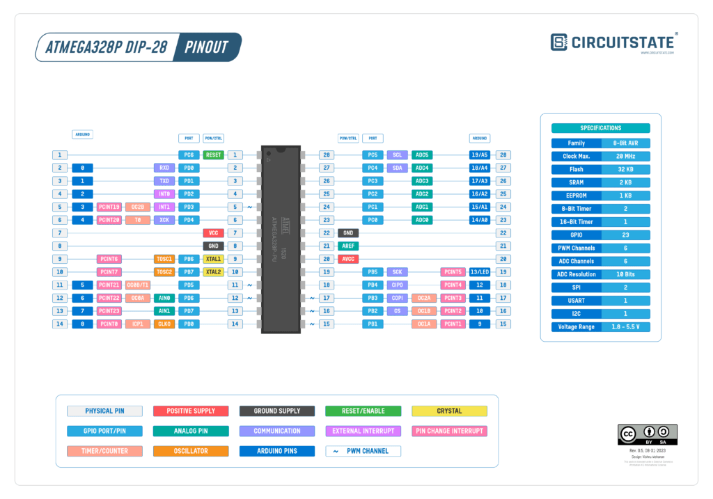
Pinout Diagram
Latest Revision: r0.5, 08-01-2023
Design by: Vishnu Mohanan
License: CC-BY-SA 4.0
Pinouts are based on the latest documentation from the manufacturer. While we try our best to be accurate and up-to-date here, we can not guarantee correctness. Please also double-check the pin assignments with that from the official documentation. If you found any errors here, please let us know in the comments. We will update our designs ASAP.
PNG

Even though only Arduino digital pins are shown, all other peripheral pins have the same functions in the Arduino environment.
PDF preview may not load on mobile devices. Click the link to open an interactive preview, or download it directly.
Pin Reference
Power & Control
VCC & GND
These are the main supply pins. All GND pins should be connected together. VCC supply can range from 1.8V to 5.5V. Changing the voltage will also change the maximum clock frequency the microcontroller can run reliably. Check the datasheet for more info.
XTAL
XTAL1 and XTAL2 are the pins for providing external clock signals to the microcontroller. A crystal oscillator can be connected to these pins along with capacitors. The fuses also need to be configured to select an external oscillator. If you have an external clock source, it can be connected to XTAL1 while leaving XTAL2 floating. Both pins have IO functions, but those functions can be not used while the pins are used for clock input. See “Alternate Functions of Port B” in the datasheet for more info.
AVCC
AVCC is the supply pin for the internal ADC of ATmega328P. This pin should be connected to VCC externally along with a filter capacitor, even if the ADC is not used. You could connect a low-noise supply to this pin, but in that case, the supply voltage must not differ from the VCC by more than ±0.3V.
AREF
The ATmega328P has two options for the ADC reference voltage; an internal reference of 1.1V (nominal) and AVCC supply. The AREF pin is used to decouple the ADC reference voltage for better noise performance.
RESET
RESET is an active-low external reset input for ATmega328P. This pin is usually pulled up with a 10K resistor and a 0.1uF capacitor connected to GND. A LOW pulse of 2.5 μs or longer can reset the MCU (without the capacitor). RESET also has GPIO function but it can only be used when the external reset function is disabled.
Arduino Pins
Below are Arduino pin assignments used for the official Arduino Uno board with an ATmega328P. If you are new to Arduino, we have a complete tutorial covering the basics of the Arduino development framework (ADF) using the popular Arduino Uno board.
Getting Started with Arduino – Beginner’s Tutorial to Open-Source Hardware Prototyping with Arduino Uno
GPIO
Even though ATmega328P has 23 GPIOs, only 20 are available in the Arduino framework. Some alternate function pins are excluded. All GPIO pins support internal pull-ups in the range of 20-50K.
| Pin # | Pin Name | Arduino Digital Pin |
|---|---|---|
| 2 | PD0 | 0 |
| 3 | PD1 | 1 |
| 4 | PD2 | 2 |
| 5 | PD3 | 3 |
| 6 | PD4 | 4 |
| 11 | PD5 | 5 |
| 12 | PD6 | 6 |
| 13 | PD7 | 7 |
| 14 | PB0 | 8 |
| 15 | PB1 | 9 |
| 16 | PB2 | 10 |
| 17 | PB3 | 11 |
| 18 | PB4 | 12 |
| 19 | PB5 | 13 |
| 23 | PC0 | 14 |
| 24 | PC1 | 15 |
| 25 | PC2 | 16 |
| 26 | PC3 | 17 |
| 27 | PC4 | 18 |
| 28 | PC5 | 19 |
LED
Arduino Uno has an onboard LED for debugging. This LED is connected to digital pin 13. You can access the LED pin as LED_BUILTIN in the Arduino IDE.
UART
ATmega328P has only 1 UART and the TXD and RXD pins are connected to the USB-Serial chip on an Arduino Uno. If you need extra UART ports, you can consider using the SoftwareSerial library. Hardware flow control pins (CTS, RTS) are not available in the Arduino framework.
| Pin # | Digital Pin | Function | Arduino Instance |
|---|---|---|---|
| 2 | 0 | TXD | Serial |
| 3 | 1 | RXD | Serial |
SPI
There are two SPI (Serial Peripheral Interface) ports available in ATmega328P but one is shared with the UART. So only one SPI interface is usable.
| Pin # | Digital Pin | Function | Arduino Instance |
|---|---|---|---|
| 17 | 11 | COPI | SPI |
| 18 | 12 | CIPO | SPI |
| 19 | 13 | SCK | SPI |
| 16 | 10 | CS | SPI |
I2C
There is only one I2C (Inter-Integrated Circuit) interface available in ATmega328P. The I2C pins also share ADC input functions. You can only use one function at a time. I2C is also called Wire in the Arduino environment.
| Pin # | Digital Pin | Function | Arduino Instance |
|---|---|---|---|
| 27 | 18 | SDA | Wire |
| 28 | 19 | SCL | Wire |
ADC
ATmega328P has a single 10-bit ADC with 6 multiplexed channels. The maximum sampling rate is 15 ksps. There are two additional inputs AIN0 and AIN1 used for analog comparator inputs.
| Pin # | Digital Pin | Arduino ADC Pin |
|---|---|---|
| 23 | 14 | A0 |
| 24 | 15 | A1 |
| 25 | 16 | A2 |
| 26 | 17 | A3 |
| 27 | 18 | A4 |
| 28 | 19 | A5 |
PWM
The hardware timer blocks of ATmega328P can be used to generate PWM (Pulse Width Modulation) of varying duty cycles and frequencies. PWM output is supported by 6 pins in the Arduino environment, labeled as OCxx on the pinout diagram. You can use the analogWrite() function to output the PWM waveform. You can learn more about Arduino Uno PWM from – Secrets of Arduino PWM.
| Pin # | Digital Pin | Frequency (Hz) |
|---|---|---|
| 5 | 3 | 490 |
| 11 | 5 | 980 |
| 12 | 6 | 980 |
| 15 | 9 | 490 |
| 16 | 10 | 490 |
| 17 | 11 | 490 |
External Interrupts
There are only two external interrupt pins available on ATmega328P called INT0 and INT1. These interrupts can detect FALLING, RISING, LOW or CHANGE triggers. But all GPIO ports also have common change interrupt capability. The change interrupt can be generated by any pins of a port, and such pins are labeled as PCINTxx on the pinout diagram.
| Pin # | Digital Pin | Function |
|---|---|---|
| 4 | 2 | INT0 |
| 5 | 3 | INT1 |
Links
Short Link
- Short URL to the page – https://circuitstate.com/atm328pdip28pin


