Milk-V Duo 64M RISC-V Linux Development Board – Pinout Diagram & Arduino Reference
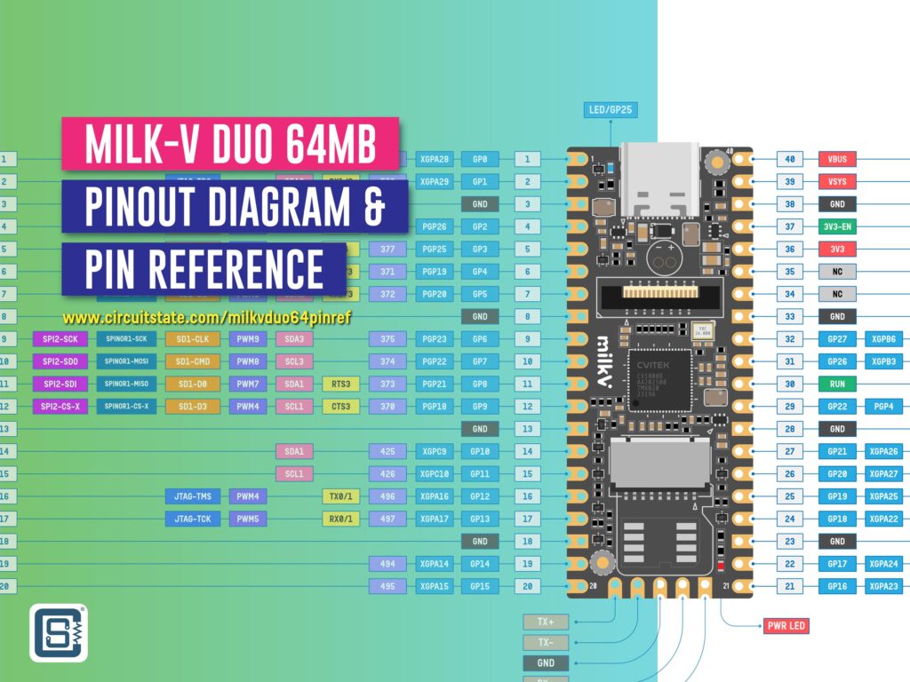
Complete pinout reference for the Milk-V Duo-64M Linux and Arduino development board including Arduino pin and interface references.

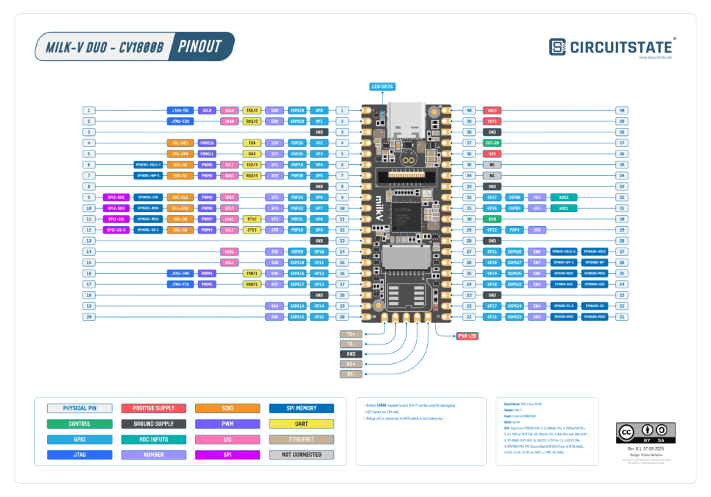
The Duo 64M from Milk-V is a dual-core RISC-V SoC capable of running the Linux operating system. It can also run your Arduino sketches at the same time. We have designed a beautiful vector pinout diagram for the Milk-V Duo 64M board. We have tried our best to keep as many details as accurate as possible here. But due to the insufficient official documentation, there could be a few things that are out of place. In case you find any errors, please let us know in the comments and we will improve them. If you want to get started with the Milk-V Duo board for Linux and Arduino development, follow our getting started tutorial.
Getting Started with Milk-V Duo – RISC-V Linux Development Board
General Pinout
- Filename: Milk-V-Duo-64M-General-Pinout-R0.1-CIRCUITSTATE-Electronics-1.pdf
- Latest Revision: R0.1, 07-08-2025
- Designed by: Vishnu Mohanan (@vizmohanan, @vishnumaiea)
- License: CC-BY-SA 4.0
Pinouts are based on the latest documentation from Milk-V. While we try our best to be accurate and up-to-date here, we can not guarantee correctness. Please also cross verify the pin assignments with that from the official documentation. If you found any errors here, please let us know in the comments and will update our designs.
PNG

This pinout is only applicable for Linux development with the board. For development with Arduino, use the Arduino pinout diagram. Also, there are subtle differences between the 64MB and the 256MB versions of the Duo board. Therefore, you must use the pinouts for the specific variant. Following are the notes added to the pinout diagram.
- Default
UART0mapped to pins 16 & 17 can be used for debugging. - ADC inputs are 1.8V only.
- Debug LED is connected to
GP25which is not broken out.
PDF preview may not load on mobile devices. Click the link to open an interactive preview, or download it directly.
Arduino Pinout
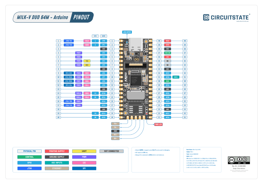
- Filename: Milk-V-Duo-64M-Arduino-Pinout-R0.1-CIRCUITSTATE-Electronics-1.pdf
- Latest Revision: R0.1, 15-08-2025
- Designed by: Vishnu Mohanan (@vizmohanan, @vishnumaiea)
- License: CC-BY-SA 4.0
This Pinouts are based on the latest documentation from Milk-V. While we try our best to be accurate and up-to-date here, we can not guarantee correctness. Please also cross verify the pin assignments with that from the official documentation. If you found any errors here, please let us know in the comments and will update our designs.
PNG

This pinout is only applicable for Arduino development with the Duo board. For development with Linux, use the General pinout diagram. Also, there are subtle differences between the 64MB and the 256MB versions of the Duo board. Therefore, you must use the pinouts for the specific variant. Following are the notes added to the pinout diagram.
- Default
UART0mapped to pins 16 & 17 can be used for debugging. - ADC inputs are 1.8V only.
- Debug LED is connected to
GP25which is not broken out.
Pinout Reference
This pinout reference is only applicable for the Arduino pinout. The general mapping and the Arduino mapping of the pins are different in many places. There is also a lack of sufficient documentation. So if you run into any issues while using our references, please let us know. If you want to know the entire pin definition and assignments check the variant_pins.h file.
Power & Control
There are two positive power supply input pins and one control pin on the Milk-V Duo-64M.
| Pin Name | Function |
|---|---|
VBUS | The USB 5V input. This will be connected to VSYS via a diode. You can supply 5V directly here if the USB is not connected. |
VSYS | The output coming through the VBUS diode. You can supply 5~12V here. |
3.3V | Output from the MP1657 DC-DC voltage regulator. This is an output only. The maximum current can be up to 2A. |
3V3-EN | Enables the main 3.3V/2A supply. Proving a HIGH signal here will disable the 3.3V output. |
GND | Ground (Negative) supply pins. |
RUN | This is the reset pin. Connecting this pin to HIGH will reset the board. |
GPIO
Even though the Milk-V Duo 64M breaks out 25 GPIO pins from the SoC, only 6 pins are assigned in the official pinout diagram. This is probably because of the limitation of the second C906 core running the Arduino sketch.
LED
The blue LED on the board is connected to GPIO25. You can access this pin in Arduino by using the GPIO number 0.
UART
You only get a single UART (Universal Asynchronous Receiver Transmitter) when using the Arduino core. You can use this to communicate with a sensor or a PC using a UART-USB converter.
| Arduino Instance | UART | RX Pin | TX Pin |
|---|---|---|---|
Serial3 | UART3 | RX3 (GP5) | TX3 (GP4) |
SPI
There is a single instance of SPI (Serial Peripheral Interface) available for Arduino sketches.
| Arduino Instance | SPI | COPI | CIPO | SCK | CS |
|---|---|---|---|---|---|
SPI | SPI2 | GP7 | GP8 | GP6 | GP9 |
ADC
There is a single ADC (Analog to Digital Converter) input pin available for the Milk-V Duo-64M board. The maximum input voltage of this pin is 1.8V. If you want to provide a larger input voltage, use a voltage divider.
| Arduino Pin | GPIO |
|---|---|
A0 | ADC1 (GP26) |
I2C
We get four I2C (Inter-Integrated Circuit) interfaces on the Milk-V Duo-64M board. These can be accessed as Wire0 to Wire3.
| Arduino Instance | I2C | SDA | SCL |
|---|---|---|---|
Wire (Wire0) | I2C0 | 2 (GP1) | 1 (GP0) |
Wire1 | I2C1 | 11 (GP8) | 12 (GP9) |
Wire2 | I2C2 | 14 (GP10) | 15 (GP11) |
Wire3 | I2C3 | 9 (GP6) | 10 (GP7) |
PWM
There are 8 PWM channels and 12 PWM pins from the Milk-V Duo-64M board. This is because some of the channels are available in multiple GPIO pins.
| Channel | Pin # | Pin Name |
|---|---|---|
PWM4 | 12 | GP9 |
| 16 | GP12 | |
PWM5 | 6 | GP4 |
| 17 | GP13 | |
PWM6 | 5 | GP3 |
| 7 | GP5 | |
PWM7 | 4 | GP2 |
| 11 | GP8 | |
PWM8 | 10 | GP7 |
PWM9 | 9 | GP6 |
PWM10 | 14 | GP10 |
PWM11 | 15 | GP11 |
JTAG
JTAG (Joint Test Action Group) is a standard interface used for programming and debugging microcontrollers. Milk-V Duo-64M supports JTAG programming and debugging. JTAG has four main signals and an optional reset line.
| Signal Name | Pin Name | Pin # | Function |
|---|---|---|---|
TDI | GP0 | 1 | Test Data In |
TCK | GP13 | 17 | Test Clock |
TMS | GP12 | 16 | Test Mode Select |
TDO | GP1 | 2 | Test Data Out |
Links
- Milk-V Duo – Product Page
- Milk-V Duo – Datasheet [PDF]
- Milk-V Duo – Hardware Design Resources
- Milk-V Duo – Documentation
- Buy Milk-V Duo – Robu.in
- Duo SDK – GitHub
- Balena Etcher
Short Link
- Short URL to this page – https://circuitstate.com/milkvduo64pinref


