MAX485-CD4069 RS-485 Module with Auto Data Direction Control – Pinout Diagram & Reference
Complete pinout diagram and pin reference for the MAX485-CD4069 RS-485 communication module with automatic data direction control.
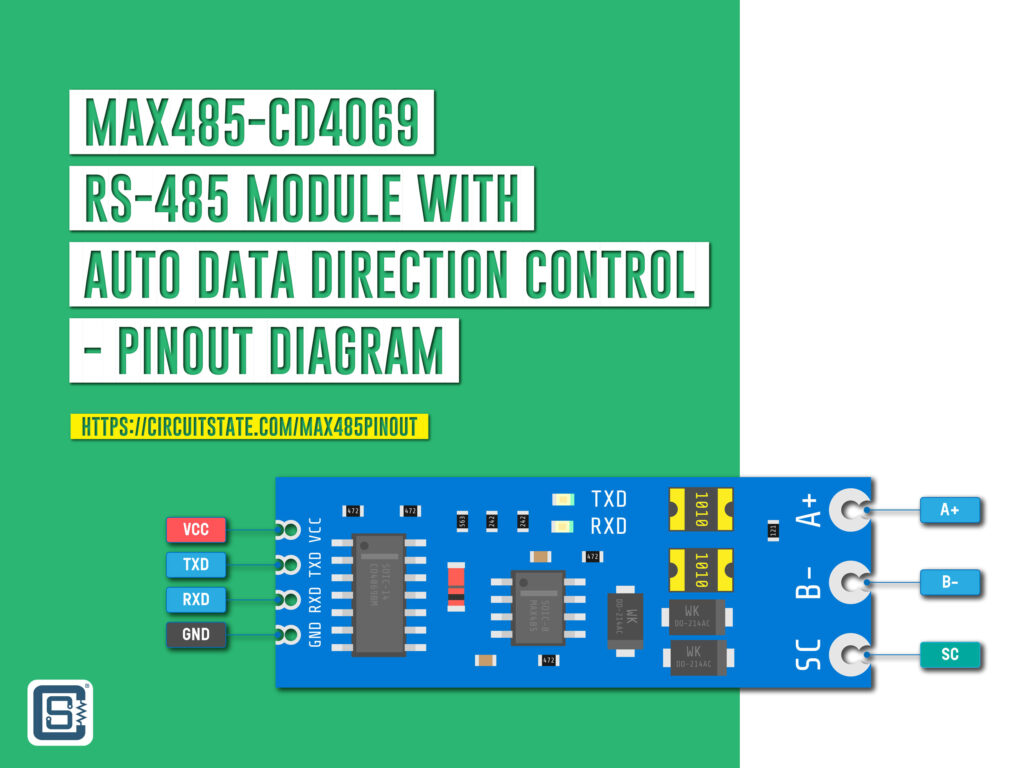
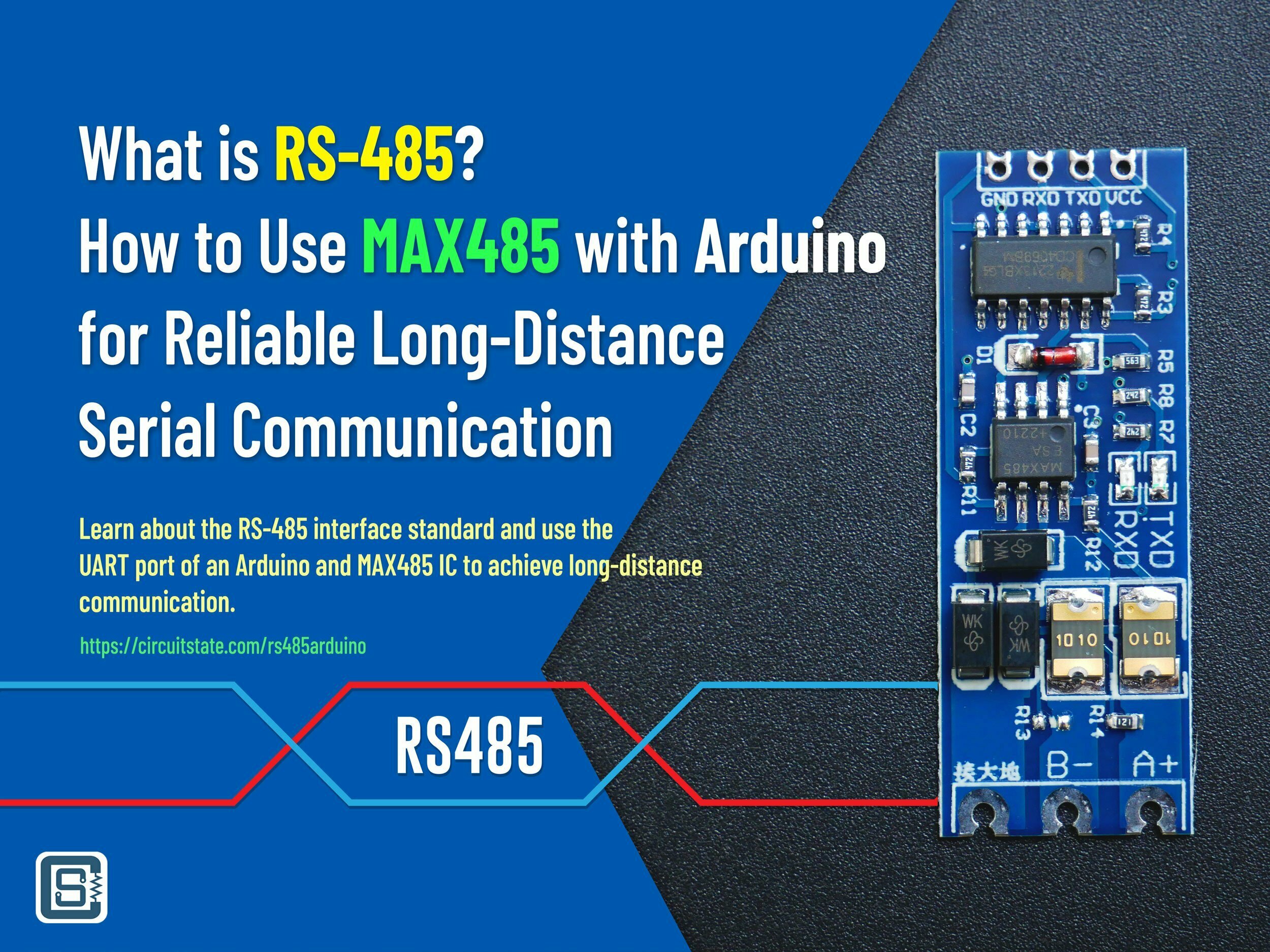
MAX485 from Maxim is a low-power transceiver intended for RS-485 and RS-422 applications. It is a half-duplex driver with a Unit Load (UL) rating of 1 and therefore you can have up to 32 MAX485s on a single RS-485 bus. The data rate is up to 2.5 Mbps. MAX485 is available in 8-pin packages of various forms and the typical supply voltage is 5V. Its IO voltage is also 5V which means you can interface it directly to any 5V microcontroller. There are many easy-to-interface breakout modules available for using MAX485 in your applications. One such module is the one that combines a MAX485 with a CD4069 hex inverter. The module features auto data direction control which eliminates the need for two extra GPIO pins. Instead, the direction of data transmission is automatically determined by the RX and TX pins states. So you only need the power supply lines and the TX and RX lines for interfacing. We have an in-depth RS485 communication tutorial using the same module which you can find below.
What is RS-485 & How to Use MAX485 with Arduino for Reliable Long-Distance Serial Communication
MAX485 Specifications
| Parameter | Value |
|---|---|
| Configuration | Half-Duplex |
| Data Rate | 2.5 Mbps |
| Data Rate at 1200 m | 110 Kbps |
| Slew-rate Limited | No |
| Quiescent Current | 300 uA |
| Number of receivers on the bus | 32 (1 UL) |
| Pin Count | 8 |
| Working Voltage | 3 – 12 V (5V typical) |
Need RS-485 or Modbus for your project?
CIRCUITSTATE can design and develop complete electronic products incorporating communication interfaces and protocols like RS-485, RS-232, 4-20mA, HART, Ethernet, MODBUS, etc. on all hardware platforms and frameworks, with robust performance. Contact us today to share your requirements.

MAX485 Pinout

| Signal Name | Description |
|---|---|
A | Non-inverting Signal |
B | Inverting Signal |
DI | Driver Input |
RO | Receiver Output |
DE | Driver Enable |
RE | Receiver Enable (Active LOW) |
VCC | Positive supply voltage |
GND | Negative supply voltage |
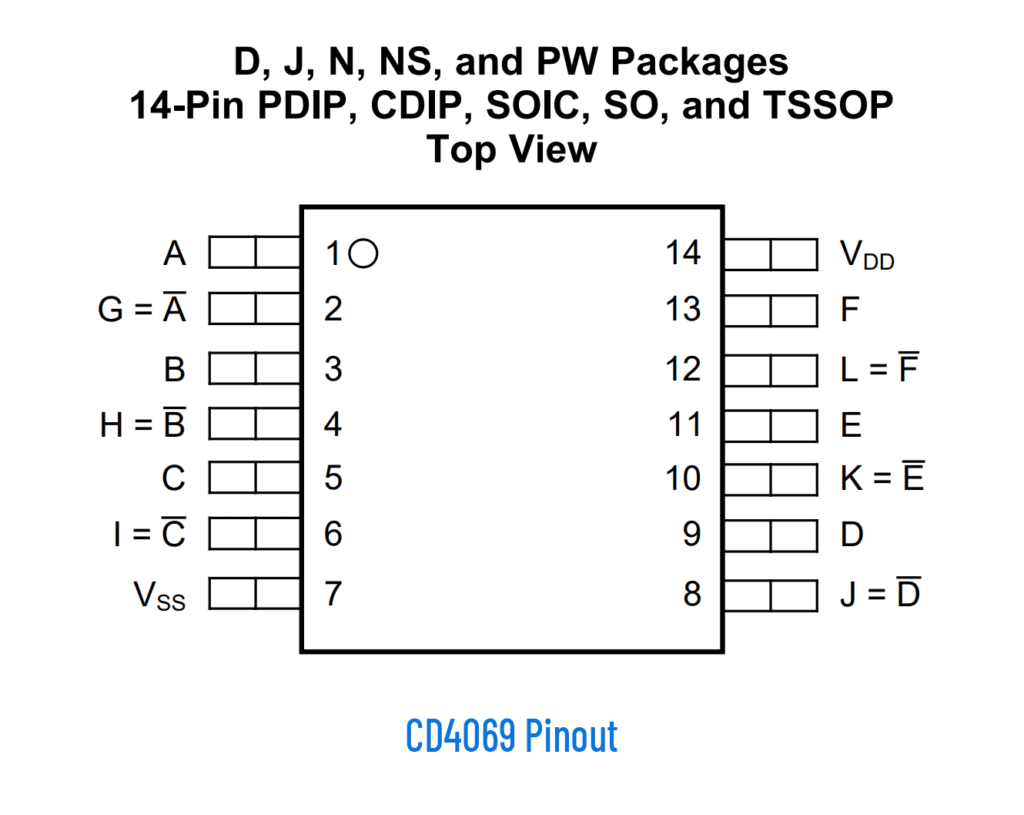
CD4069 Pinout
Pinout Diagram
Latest Revision: Rev 0.1, 07-12-2022
Designed by: Vishnu Mohanan
License: CC-BY-SA 4.0
Pinouts are based on the latest documentation from the manufacturer. While we try our best to be accurate and up-to-date here, we can not guarantee correctness. Please also double-check the pin assignments with that from the official documentation. If you found any errors here, please let us know in the comments and we will update our designs.
PNG
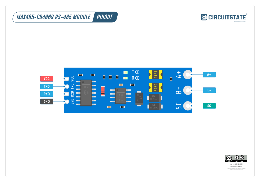
PDF preview may not load on mobile devices. Click the link to open an interactive preview, or download it directly.
Pin Reference
| RS-485 Module | Description |
|---|---|
VCC | Positive supply voltage |
GND | Ground |
RXD | Module data receive pin. Send data through this pin. |
TXD | Module data transmit pin. Read data from this pin. |
A+ | Positive line of RS-485 |
B- | Negative line of RS-485 |
SC | Signal Common |
When connecting one RS-485 module another RS-485 module you must only connect the A+, B- and SC lines. You don’t necessarily to share the VCC or GND supplies.
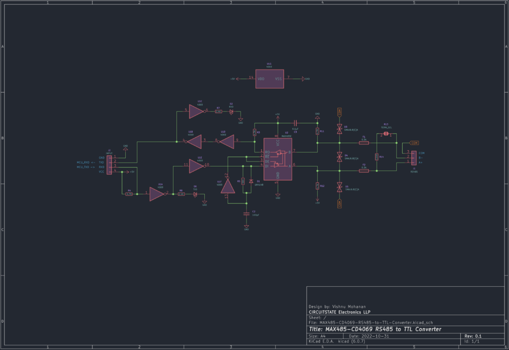
Schematic
Since an official pinout diagram is not available for the module, we reverse-engineered one using KiCad.
Links
- What is RS-485 & How to Use MAX485 with Arduino for Reliable Long-Distance Serial Communication – CIRCUITSTATE Electronics
- MAX485 – Datasheet [PDF]
- CD4069 Hex Inverter – Datasheet [PDF]
- Original TIA/EIA-485 Standard Specification [PDF]
- RS-485 Serial Interface Explained – CUI Devices
- Explanation of Maxim RS-485 Features – Analog Devices
- RS485 Cabling – Why you need 3 wires for 2-wire RS485?
- Basics of RS-485 – Texas Instruments [PDF]
- RS-422 / RS-485 Industrial Standards
- What is RS-485 and how is it used in industrial control systems? – RealPars
- How do I wire RS485 devices? – Innon
- Wiring of RS485 Communications Networks – Schneider Electric
Short Link
- Short URL to this page – https://www.circuitstate.com/max485pinout
