Interfacing Silicon Labs CP2102 USB-to-UART Serial Converter Module
When it comes to communicating with a microcontroller, the word “serial” just pops up into mind if you’re familiar with microcontrollers. Three major communication protocols/interfaces used by microcontrollers are UART, SPI and I2C (TWI). Universal Asynchronous Receiver Transmitter (UART) as its name says, is an asynchronous serial communication protocol and almost all uC has it built-in. This is what this article is based on. So we’ll explore it in detail just after commenting on others. SPI stands for Serial Peripheral Interface and employs controller-peripheral concept. Data is still send serially but multiple devices can communicate with a controller using Chip Select (CS) pins, and it is synchronous, means it has a common clock signal SCK. I2C (read as “I squared C” or “I two C”) is a two wire communication protocol, and thus some manufactures call it Two Wire Interface (TWI) except some minor difference. Using I2C, multiple peripherals can communicate with one or more controllers. This requires only two wires, SDA (Serial Data) and SCL (Serial Clock) and of course it’s synchronous. SparkFun has great tutorials on UART, SPI and I2C. Please check that out first because here I’ll be assuming you have basic knowledge of all these.
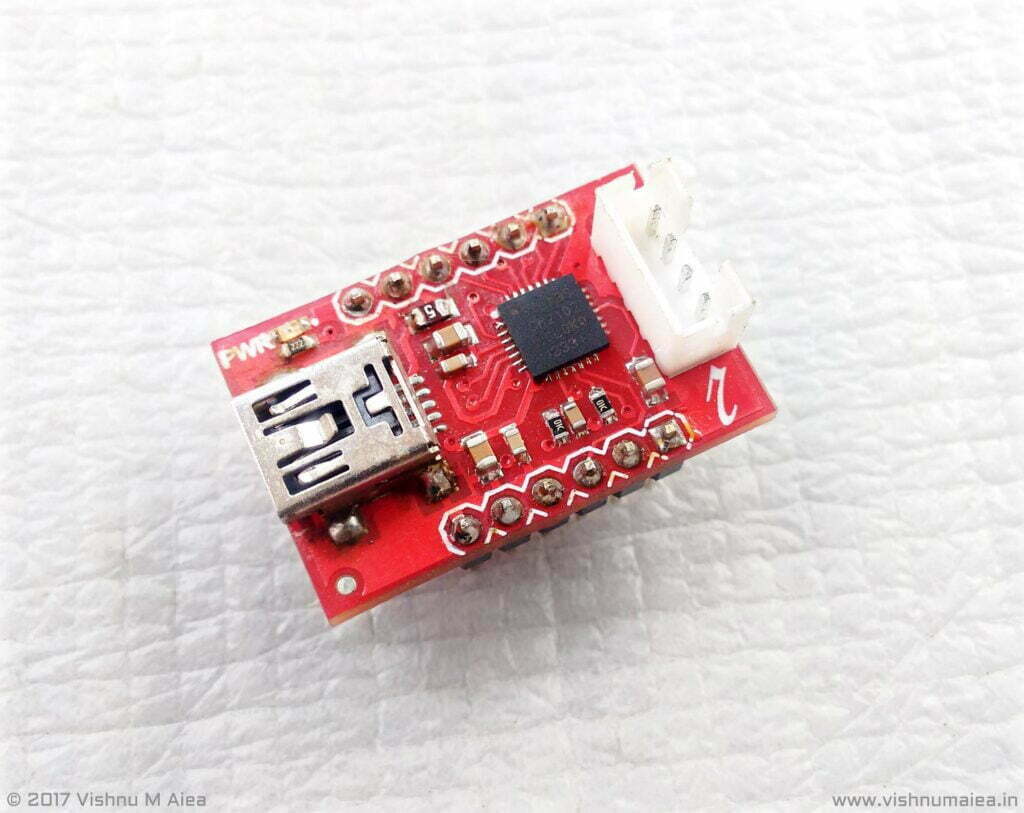
We’re going to interface a CP2102 USB to Serial breakout board from RhydoLabz with an Arduino Uno. A Uno has a USB to Serial interface controller already. The ATmega16U2 on the Uno is programmed to work as a USB host controller. The 16U2 is an MCU with built-in USB host controller, means you can directly connect it to a computer with USB. But you can’t use a 16U2 as USB controller when you want to deploy a standalone Arduino, or more specifically an ATmeag328 or similar chips with Arduino firmware and minimal components. We can’t connect the RX and TX pins of Arduino directly with a computer unless you have physical Serial COM Port or an RS-232 port, and a level shifting circuit. RS-232 is a legacy communication port that most old computers used to have, but now superseded by interfaces such as USB. So nobody uses COM ports these days and no computers come with them today. These are the reasons why we need a USB to serial converter.
The most famous USB to Serial chip is the FT232RL from FTDI. But these chips are overpriced. More cheap USB-UART chips available on the market are CP2102 and CH340G, the latter being the cheapest. The CP2102 is a full speed USB 2.0 to UART chip from Silicon Labs. The CP2102 integrates everything required to implement a USB-UART system, including internal oscillator, on-chip voltage regulator etc and comes in QFN-28 SMD package. It works with 3.3V supply, but the internal voltage regulator enables it to be USB powered. Following is the block diagram and pinout of CP2102.
| Pin No. | Pin Name | Type | Description |
| 6 | VDD | 3.3V Input/Output | This is either 3.3V input or 3.3V ouput from regulator. |
| 3 | GND | Ground supply | |
| 9 | RST | I/O | Device reset. This is either POR or active low reset input. |
| 7 | REGIN | Power In | 5V input for on-chip 3.3V regulator. |
| 8 | VBUS | Input | VBUS Sense input is connected to 5V from USB to detect USB power. |
| 18 | NC | Not Connected | |
| 4 | D+ | I/O | USB D+ data line |
| 5 | D- | I/O | USB D- data line |
| 26 | TXD | Output | UART Transmit |
| 25 | RXD | Input | UART Receive |
| 23 | CTS | Input | Clear To Send control (active low) |
| 24 | RTS | Output | Ready to Send control output (active low) |
| 27 | DSR | Input | Data Set Ready control input (active low) |
| 28 | DTR | Output | Data Terminal Ready control output (active low) |
| 1 | DCD | Input | Data Carrier Detect control input (active low) |
| 2 | RI | Input | Ring Indicator control input (active low) |
| 12 | SUSPEND High | Output | USB suspend state (active high) |
| 11 | SUSPEND Low | Output | USB suspend state (active low) |
| 10, 13-22 | NC | Not Connected |
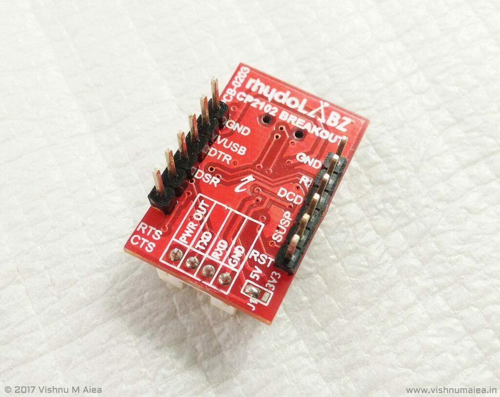
We don’t need CTS, RTS, DSR, DTR, DCD and RI as they’re RS-232 specific pins. We just need the RXD and TXD pins. Connect the TXD to RX of Arduino and RXD to TX of the Arduino. The breakout board has a 5V or 3.3V selector jumper which is connected to 5V USB supply by shorting the POWER OUT pin to VBUS. If you want to power a 3.3V Arduino from it, you must set it to 3V3. The chip is always bus powered as the REGIN is connected to VBUS.
The internal EEPROM of the CP2102 can be programmed to store device specific parameters like product ID, serial number, product description etc. Refer to the datasheet for more details.
Installing the Driver
Once you’re done with wiring, connect the breakout board to computer via Mini-USB cable. In order for the CP2102 to communicate to your PC and the PC to back to the chip, we need a Virtual COM Port (VCP) driver. I said earlier that computers used to have standard serial ports. Even if a computer doesn’t have a physical serial port or have one or two, the operating system can emulate these serial ports as if there were multiple physical serial ports present. This software emulated serial ports are called Virtual COM Ports. That’s just the CP2102 driver is going to do. It’ll tell the OS to create a VCP and assign it to our connected device. The drivers can be downloaded from Silab’s website and RhydoLabz has put together a nice driver installation guide here.
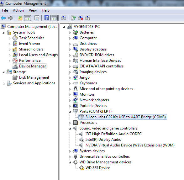
Once you have installed the drivers properly, you’ll see COM port of any number greater than 2 is assigned to your device, since COM1 and COM2 are usually reserved. If there are no VCP devices connected, you’ll probably get COM3. But what if there are multiple VCP devices ? How do you determine which one is your device ? In that case, you need some kind of authentication mechanism in your code to identify your device probably by polling. But polling isn’t always a good idea because you could end up freezing a device with unknown command.
If you have identified the COM port of your device, then you can start communicating via any serial terminal programs like Hyperterminal, PuTTY, Arduino serial monitor, Processing code etc.
PS : Kerry D. Wong has a “CP2102 DIY USB-to-Serial converter” used with a standalone Arduino compatible board and a tutorial on how to use a “CP2102 breakout board as Arduino Programmer“.
